Key Takeaway: Learn how to build a multi-channel temperature monitoring system using STM32F103C8 (Blue Pill) and DS18B20 digital temperature sensors communicating over the 1-Wire bus protocol with an I2C LCD display for real-time readout.
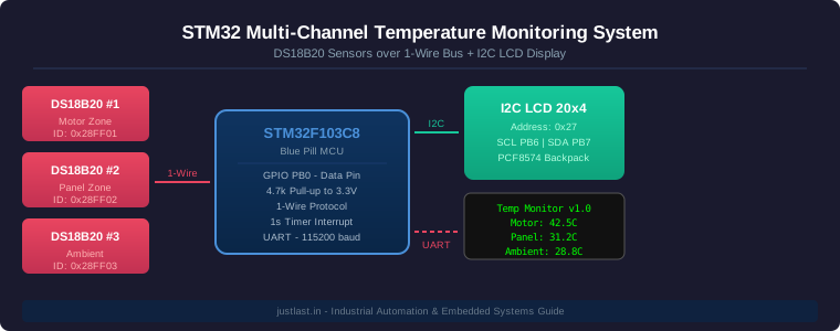
Table of Contents
1. System Overview
Industrial temperature monitoring is critical for protecting equipment and ensuring process quality. The DS18B20 is a digital temperature sensor that offers ±0.5°C accuracy from -10°C to +85°C, making it ideal for monitoring motor drives, control panels, and ambient conditions in a manufacturing environment.
Each DS18B20 has a unique 64-bit ROM code that enables multiple sensors to share a single microcontroller pin using the 1-Wire protocol. This means you can monitor dozens of temperature zones with just one GPIO pin on your STM32. The STM32F103C8 (Blue Pill) processes the readings and displays them on an I2C 20×4 LCD, providing an at-a-glance status of all monitored zones.
This project demonstrates a practical STM32 temperature monitoring system suitable for factory floor deployment, CNC machine monitoring, or server room temperature tracking.
2. Hardware Required
- STM32F103C8T6 (Blue Pill) development board
- 3x DS18B20 temperature sensors (TO-92 package)
- 4.7kΩ resistor (1/4W)
- I2C LCD 20×4 display with PCF8574 backpack
- Breadboard and jumper wires
- USB to UART converter (FT232 or CP2102)
- 3.3V power supply
3. Wiring Diagram
DS18B20 Connections (1-Wire Bus):
- Each DS18B20 VDD (red) → 3.3V rail
- Each DS18B20 GND (black) → GND rail
- Each DS18B20 DATA (yellow/white) → STM32 PB0
- 4.7kΩ resistor between 3.3V and DATA line (pull-up)
Important: The 4.7kΩ pull-up resistor is non-negotiable. Without it, the 1-Wire bus will not function correctly. If you are connecting long cable runs (over 5 meters), consider using a 2.2kΩ resistor instead and add a 100nF bypass capacitor at each sensor.
I2C LCD Connections:
- LCD VCC → 3.3V
- LCD GND → GND
- LCD SDA → STM32 PB7 (I2C1 SDA)
- LCD SCL → STM32 PB6 (I2C1 SCL)
4. STM32 Firmware Implementation
The firmware uses the STM32 Standard Peripheral Library. The 1-Wire protocol is implemented with bit-banged GPIO timing since STM32’s standard peripherals don’t include native 1-Wire support. We use SysTick timer interrupts to sample temperatures every second.
4.1 GPIO Configuration
// PB0 as open-drain output for 1-Wire
GPIO_InitTypeDef GPIO_InitStructure;
GPIO_InitStructure.GPIO_Pin = GPIO_Pin_0;
GPIO_InitStructure.GPIO_Mode = GPIO_Mode_Out_OD;
GPIO_InitStructure.GPIO_Speed = GPIO_Speed_50MHz;
GPIO_Init(GPIOB, &GPIO_InitStructure);
4.2 1-Wire Timing Functions
The 1-Wire protocol relies on precise timing. A write 1 slot is 2-15µs low followed by 60-120µs high. A write 0 slot is 60-120µs low. The reset pulse is 480µs low followed by 480µs wait for presence pulse. These timings are critical for reliable communication.
// 1-Wire Reset
uint8_t OW_Reset(void) {
    uint8_t presence = 0;
    OW_LOW();
    delay_us(480);
    OW_HIGH();
    delay_us(70);
    presence = GPIO_ReadInputDataBit(GPIOB, GPIO_Pin_0) ? 0 : 1;
    delay_us(410);
    return presence;
}

// Read one byte from 1-Wire bus
uint8_t OW_ReadByte(void) {
    uint8_t data = 0;
    for (uint8_t i = 0; i < 8; i++) {
        data >>= 1;
        if (OW_ReadBit()) data |= 0x80;
    }
    return data;
}
4.3 Temperature Conversion Routine
float ReadDS18B20(uint8_t *rom) {
    uint8_t scratchpad[9];
    OW_Reset(); OW_SkipROM();
    OW_WriteByte(0x44); // Start conversion
    delay_ms(750);      // Wait 750ms (max conversion time at 12-bit)
    OW_Reset(); OW_MatchROM(rom);
    OW_WriteByte(0xBE); // Read scratchpad
    for (uint8_t i = 0; i < 9; i++)
        scratchpad[i] = OW_ReadByte();
    int16_t temp = (scratchpad[1] << 8) | scratchpad[0];
    return temp * 0.0625f;
}
Important tip: Always wait at least 750ms for the temperature conversion when using 12-bit resolution. If you need faster sampling, you can configure the sensor for 9-bit resolution (93.75ms conversion time) by writing the configuration register. However, 12-bit mode provides 0.0625°C resolution which is preferable for industrial monitoring.
5. I2C LCD Integration
The PCF8574 I2C backpack converts I2C serial data to parallel signals for the LCD. The default I2C address is 0x27. Initialization sequence must follow the HD44780 datasheet timing requirements.
void LCD_Init(void) {
    delay_ms(50);  // Wait for LCD power-up
    LCD_WriteNibble(0x30, 0); delay_ms(5);
    LCD_WriteNibble(0x30, 0); delay_us(150);
    LCD_WriteNibble(0x30, 0);
    LCD_WriteNibble(0x20, 0); // Set to 4-bit mode
    LCD_WriteCmd(0x28); // 2 lines, 5x8 font
    LCD_WriteCmd(0x0C); // Display on, cursor off
    LCD_WriteCmd(0x06); // Auto-increment
    LCD_WriteCmd(0x01); // Clear display
    delay_ms(2);
}

void DisplayTemperatures(float t1, float t2, float t3) {
    char line1[21], line2[21], line3[21], line4[21];
    sprintf(line1, "Motor Drive:  %5.1fC", t1);
    sprintf(line2, "Control Pan:  %5.1fC", t2);
    sprintf(line3, "Ambient:      %5.1fC", t3);
    sprintf(line4, "Updated: %s", GetTimeString());
    LCD_SetCursor(0, 0); LCD_WriteString(line1);
    LCD_SetCursor(0, 1); LCD_WriteString(line2);
    LCD_SetCursor(0, 2); LCD_WriteString(line3);
    LCD_SetCursor(0, 3); LCD_WriteString(line4);
}
6. Testing and Calibration
After uploading the firmware to your STM32, verify the system step by step:
- Check sensor presence: Open the serial monitor at 115200 baud. You should see “DS18B20 detected” for each sensor found on the bus.
- Verify ROM codes: Each sensor has a unique 64-bit ROM code. Log these — you will need them for MatchROM commands when addressing specific sensors.
- Room temperature check: All sensors should read within 1-2°C of each other at room temperature.
- Heat test: Warm one sensor with your finger — the reading should change within 1 second.
- LCD output: Verify each zone name and temperature display correctly on the 20×4 LCD.
Frequently Asked Questions
How many DS18B20 sensors can I connect to one STM32 pin?
In theory, the 1-Wire protocol supports up to 256 sensors on a single bus. In practice, with the STM32F103C8 running at 72MHz, you can reliably connect 10-20 sensors. Beyond that, you may need to add a stronger pull-up resistor or use a 1-Wire bus driver like the DS2482-100.
Can I use parasitic power mode?
Yes, DS18B20 sensors can operate in parasitic power mode by connecting VDD to GND. However, for reliable industrial STM32 temperature monitoring, external power is recommended — especially when using long cable runs or more than 5 sensors on the bus.
What is the maximum cable length for 1-Wire?
With proper termination, the Dallas 1-Wire protocol can operate over cables up to 100 meters. For runs longer than 10 meters, use a 2.2kΩ pull-up resistor and consider adding a DS2480B serial interface for stronger drive capability.
Why is my LCD showing garbled characters?
This is usually a voltage level issue. The PCF8574 backpack requires a clean 5V supply, but the STM32 Blue Pill operates at 3.3V. Use a logic level converter or power the LCD separately from a 5V source. Also verify the I2C address — many PCF8574 modules use 0x27 but some use 0x3F.
How do I get 0.5°C accuracy from DS18B20?
The DS18B20 is specified for ±0.5°C accuracy between -10°C and +85°C when using the default 12-bit conversion mode. For the best accuracy, ensure proper thermal contact, avoid self-heating by keeping the conversion current low, and calibrate against a known reference at your operating temperature.
Related Reading
- STM32 Blue Pill Pinout Guide
- I2C Communication Protocol for STM32 and Arduino
- Digital Multimeter Guide for Beginners
Sources
- Maxim Integrated DS18B20 Datasheet
- STMicroelectronics STM32F103C8 Datasheet
- Texas Instruments 1-Wire Communication Guide
- HD44780 LCD Controller Datasheet
Disclosure: This post contains affiliate links. We may earn a small commission when you purchase through these links at no extra cost to you.