Key Takeaway: UART serial communication is the simplest and most widely used two-wire protocol between microcontrollers and industrial devices — once you appreciate TX/RX crossover wiring, shared ground, and matching baud rate, debugging STM32 and Arduino links becomes predictable.
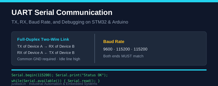
Table of Contents
1. What Is UART Serial Communication?
UART (Universal Asynchronous Receiver/Transmitter) is the hardware that turns parallel data inside a microcontroller into a serial stream on a pair of wires. “Asynchronous” means there is no shared clock — the two ends agree on a timing rate (the baud rate) and each frames bytes of data with a start bit, 8 data bits, one optional parity bit, and one or two stop bits. The line sits HIGH when idle, and a falling edge marks the start of a byte.
UART serial communication is the workhorse link between a PLC, an HMI, a GPS module, a fingerprint sensor, or a wireless transceiver and your MCU. On industrial boards it also forms the electrical basis of RS-232 and RS-485, where a transceiver converts the MCU’s logic-level UART into a differential or higher-voltage signal for long cable runs.
2. UART Pins on STM32 and Arduino
On an Arduino Uno, the hardware UART lives on pins 0 (RX) and 1 (TX) and is connected to the USB-serial bridge chip, so Serial.print() also drives the IDE’s Serial Monitor. On an STM32 board, each USART has several possible pin mappings you select in CubeMX — for example USART2 on PA2/PA3 or PA14/PA15 depending on the board. You generally enable the peripheral in CubeMX, set the baud rate and word length, and generate the HAL init code.
3. TX, RX Crossover and Common Ground
The classic beginner error is wiring TX to TX. UART is full-duplex and point-to-point: the transmit pin of device A must connect to the receive pin of device B, and vice versa. So connect A.TX → B.RX and A.RX → B.TX. You also must join the two grounds (GND to GND) — the receiver measures the line relative to its own ground, so a shared ground is required or the link produces garbage.
4. Understanding the Baud Rate
Baud rate is the number of signal changes per second and equals the number of bits per second for standard 8N1 frames. Common industrial defaults are 9600 and 115200 baud. Everything you want to talk to must be configured at the same baud: if one end is 9600 and the other 115200, you will see corrupted or missing bytes every time.
Higher baud = faster transfers but more sensitive to wiring length, capacitance, and noise. Below ~1 m, 115200 is safe; for longer runs, drop to 9600 or switch to RS-485.
5. UART on Arduino and SoftwareSerial
Hardware UART on the Uno communicates with the PC only. To talk to a second device (a GPS, a sensor, another MCU), use the SoftwareSerial library on any two pins:
#include <SoftwareSerial.h>
SoftwareSerial mySerial(10, 11); // RX, TX
void setup() {
  Serial.begin(115200);
  mySerial.begin(9600);
}
void loop() {
  if (mySerial.available()) Serial.write(mySerial.read());
}
Note SoftwareSerial is timing-sensitive and should not be used at very high baud or while interrupts are disabled. For robust multi-UART applications, prefer an STM32 (or a USB-UART breakout) with several hardware USARTs.
6. UART on STM32 with HAL
On STM32, configure a USART in CubeMX, then transmit and receive like this:
uint8_t msg[] = "OKrn";
HAL_UART_Transmit(&huart2, msg, sizeof(msg)-1, 100);

uint8_t byte;
HAL_UART_Receive(&huart2, &byte, 1, HAL_MAX_DELAY);
For production code use interrupt-based or DMA receive with a ring buffer so your timer PWM and motion-control loops never stall. Blocking HAL_UART_Transmit with a long timeout will starve motor timing on the same MCU.
7. Debugging UART with a Logic Analyzer
When two microcontrollers appear not to talk, a low-cost logic analyzer or oscilloscope on the TX line is the fastest diagnosis tool. You should see the line idle HIGH, a start bit, and clean 8-bit frames at the expected baud. Classic symptoms: a flat line means no transmit at all or wrong pins; stutter or shifted bytes means a baud mismatch or a missing common ground; and noisy edges on a long run mean you need lower baud, a pull-up, or an RS-485 transceiver.
8. Industrial Applications of UART
UART shows up throughout Industrial Automation: talking to a VFD over Modbus RTU (a UART/RS-485 link), reading a weigh scale or a laser sensor over a serial port, and interfacing a Wi-Fi/BLE module to an STM32 or ESP32. The same UART core powers RS-232 for short point-to-point industrial controls and RS-485 for multi-drop factory networks. Understanding UART is therefore a prerequisite for industrial buses like Modbus RTU that run on top of it.
Frequently Asked Questions
Why is my UART output gibberish on the Serial Monitor?
Nine times out of ten the baud rate in the Serial Monitor does not match what your sketch prints with Serial.begin(). Check both and make sure the monitor baud equals the code baud.
Can I connect two Arduino by direct UART?
Yes. Wire GND to GND, and RX of one to TX of the other, then set the same baud on both. SoftwareSerial on one end gives flexibility.
Is UART the same as RS-232 or RS-485?
No. UART is the internal protocol at the pins; RS-232 and RS-485 define the electrical signaling. A UART plus a level/driver chip produces RS-232 or RS-485.
Can a single UART talk to multiple devices?
Not directly with two-wire UART. For multi-drop bus you need RS-485 and an address-based protocol such as Modbus RTU.
Related Reading
- STM32 vs Arduino for Industrial Automation: Complete 2026 Guide
- MQTT for Industrial IoT: Complete Guide with ESP32 Examples
- I2C Communication Complete Guide for STM32 and Arduino
Sources
Disclosure: This post contains affiliate links. As an Amazon Associate, justlast.in may earn a commission on qualifying purchases at no extra cost to you.