Embedded Systems for Industrial Machines: MCU, Firmware and Fieldbus Architecture
Key Takeaway
Embedded systems for industrial machines succeed or fail on three things: a hardware layer sized for the environment, a firmware architecture with hard deadlines instead of hoped-for ones, and a fieldbus that carries data without carrying risk. Get those three right and the rest is detail work.
Embedded Systems for Machines: Firmware Architecture
HARDWARE
MCU with FPU and motor timers
Encoder and PWM capture
Fieldbus transceivers
Isolated I/O and watchdog
REAL-TIME LAYER
1 kHz motion or current loop
Hardware timer interrupt
DMA for encoder and bus
Deterministic priority scheme
SUPERVISORY LAYER
State machine and sequencer
Fieldbus protocol stack
Diagnostics and logging
Parameter storage
SAFETY
Independent watchdog
Fail-safe output states
CRC and message validation
Safe boot and signature check
Motion loop: 0.5 to 1 kHz
Fieldbus: 1 to 10 ms cycle
Budget 20 percent CPU headroom
Never trust the bus for safety
Figure 1: The four layers of a machine controller and the job each layer does
Table of Contents
- 1. What a Machine Controller Actually Is
- 2. The Hardware Layers of a Controller Board
- 3. Real-Time Firmware Architecture
- 4. The Three Loop Levels
- 5. Fieldbus Protocols: Moving Data Without Moving Risk
- 6. Safety and the Fail-Safe Path
- 7. EMC: Designing for the Environment You Actually Have
- 8. PCB Design for the Machine Environment
- 9. RTOS or Bare Metal
- 10. The Build, Version and Update Chain
- 11. Putting It Together in an Indian Shop
- Related Reading
- Sources
1. What a Machine Controller Actually Is
Most Indian machine builders start with a relay panel and end up needing something quite different. A hydraulic press that used to run on a cam switch and two contactors now needs closed-loop position control, a recipe table, a diagnostic log and a safe torque off. The part that does all of that is the machine controller, and it is an embedded system whether or not anybody calls it that.
The controller is not a PLC with a smaller case and it is not a PC with a touchscreen. It is a microcontroller running deterministic firmware on hardware built for the electrical environment of a machine. That distinction matters because the failure modes are different. A PLC fails by missing a scan. A machine controller fails by missing a deadline inside a 50 microsecond current loop, and the symptom is a blown IGBT rather than a stopped axis.
Embedded systems for industrial machines therefore have four separable layers, and this guide works through them in order: the hardware layer, the real-time firmware layer, the supervisory layer, and the safety layer that runs alongside all of them. The layers must not blur. A safety function implemented in application software on the same core that also runs the HMI protocol stack is not a safety function.
| Layer | Runs on | Deadline | Failure behaviour |
|---|---|---|---|
| Real-time | MCU core and hardware timers | 50 us to 1 ms | Motor trips, outputs off |
| Supervisory | Same MCU, lower priority task | 10 ms to 1 s | Machine stops, message shown |
| Communication | UART, RS485, CAN, Ethernet | 1 ms to 100 ms | Bus error, safe state |
| Safety | Separate relay or safety MCU | Hardware | STO asserted, drive off |
2. The Hardware Layers of a Controller Board
A machine controller board normally has four blocks, and the ordering of those blocks on the board is a design decision with electrical consequences.
Power input and protection. The board takes 24 V DC from the cabinet supply. That is the Indian standard for field power and it is what every proximity switch, solenoid and photoelectric sensor in the machine already uses. The input needs an EMC filter, a reverse polarity protection stage, an overvoltage clamp and a hold-up capacitor sized to survive a 20 ms supply dropout without the controller resetting. The dropout is not exotic: a contactor opening under load, or an upstream breaker bouncing, will do it. A 470 uF low-ESR capacitor on a 24 V rail holds roughly 470 uF x 24 V x 0.6 = 6.8 J of usable energy, which at a 10 W controller load buys about 680 ms, far more than the 20 ms needed.
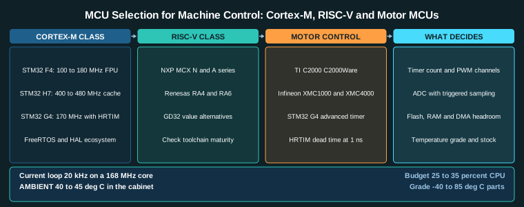
Logic core. This is the MCU, its clock, its flash and RAM, and the debug header. For machine work an Arm Cortex-M with an FPU is the default: STM32F4 and STM32H7 for general control, STM32G4 when advanced timers and fast ADC are needed, NXP MCX and Renesas RA as the alternatives. RISC-V parts from NXP and GD32 are increasingly viable but the tooling and middleware support still lags Arm in most Indian shops. The specific comparison is in the MCU selection guide.
Interfaces. Digital I/O, analogue inputs for 0 to 10 V and 4 to 20 mA, encoder counters, PWM outputs, and the fieldbus transceivers. Analogue input resolution must be matched to the signal. A 0 to 10 V process signal scaled to a 3.3 V ADC reference across an 8:1 divider uses 12 bits of a 12 bit ADC for the whole span, so the useful resolution is about 2.44 mV per count, or 0.024 percent of full scale. Any accuracy better than that is lost in the reference and the front end, not the converter.
Protection and isolation. Every field wire that leaves the cabinet can pick up an industrial surge. Digital inputs need a TVS or an RC input filter and a common mode choke for long runs. Analogue inputs need galvanic isolation if the transmitter is powered from a different source, and isolation must have a defined creepage and clearance across the barrier.
3. Real-Time Firmware Architecture
Firmware for a machine controller is not application code. It is a scheduler with deadlines, and the deadlines come from physics.
The structure that works is a three-level priority scheme. At the bottom is the interrupt layer, and it must stay short. The only things that belong in an interrupt handler are reading a capture register, pushing a buffer, and setting a flag. A current loop that reads three ADC channels, runs a transform and updates the PWM compare registers in an interrupt is workable if that interrupt is hard real-time and the handler is under 2 microseconds. The same code inside a higher priority task while the motor is on a shoddy ground is not.
In the middle is the fast task, typically 500 us to 1 ms, that runs the current and speed loops and the encoder processing. At the top is everything else: the state machine, the HMI protocol, the fieldbus protocol stack, the data log, the parameter storage.
Three rules keep this architecture honest. First, never block in the fast path. A call to a flash write routine that takes 40 ms must not be reachable from a 1 ms task, because during that 40 ms the current loop stops running and the motor is uncontrolled. Second, always measure the worst case, not the average. A loop that averages 200 us but has a 3 ms spike on a rare branch will still trip the watchdog, and it will do so once a month on a Friday. Third, budget headroom. If the fast task uses 65 percent of the CPU on average, the remaining 35 percent has to absorb the spikes, the logging and the bus traffic, and that is the difference between a machine that runs for years and a machine that needs a firmware upgrade every six months.
4. The Three Loop Levels
Almost every motor in a machine is controlled by a cascade of three loops, and each loop has a bandwidth that must be 5 to 10 times lower than the loop inside it. That rule is not a style preference; it is what makes the cascade stable.
Current loop, 10 to 20 kHz. This loop regulates the stator current that produces torque. It runs on the PWM timer and it is the fastest thing in the firmware. The PWM carrier is usually 10 to 20 kHz, above the audible range and above the bandwidth of any mechanical resonance in the machine. The current loop has to sample the shunt amplifier synchronously with the PWM, ideally at the centre of the on-time when the ripple is smallest.
Speed loop, 100 to 500 Hz. This loop takes the speed error and produces the current reference. Its bandwidth is limited by the mechanical resonances of the load, and pushing it higher produces oscillation that feels like a buzz and that no amount of gain tuning will remove.
Position loop, 10 to 100 Hz. This loop compares the commanded position from the trajectory planner with the encoder position and produces the speed reference. Its bandwidth is limited by the compliance of the drive train and by the ability of the mechanical system to follow without exciting resonance.
The ratio is the design rule: current at 20 kHz, speed at 200 Hz, position at 20 Hz. The position loop error is the following error, and a machine that scrapes parts because the following error is 0.2 mm at 500 mm/s has a position loop that is too slow for the mechanics, not a servo that is too weak.
The mechanical consequence is worth stating: bandwidth consumes stiffness. A faster position loop needs a stiffer gearbox, a better bearing and a shorter coupling, which is why the same controller on a soft linkage feels worse no matter how it is tuned. The ball screw thrust and life calculator is the right tool for checking whether the axis mechanics can actually carry the bandwidth the firmware wants.
5. Fieldbus Protocols: Moving Data Without Moving Risk
A controller that only has screw terminals can control a machine but cannot scale to one. Distributed I/O over a fieldbus reduces cabinet wiring, shortens analogue signal paths and moves the I/O electronics next to the sensors where the signal is still clean.
Two buses dominate Indian machine building and they do different jobs.
RS485 with Modbus RTU is the slow bus. It is cheap, it is available from every distributor, and it is perfect for temperature transmitters, pressure switches, and VFD parameter read-modify-write. A 2-wire RS485 network is a half-duplex multi-drop line with 120 ohm termination at both physical ends and fail-safe biasing resistors at exactly one point. The engineering detail, including the termination and biasing rules and the CAN bit-timing arithmetic, is in the fieldbus guide.
CAN with CANopen is the fast bus. PDO traffic is cyclic and deterministic, SDO traffic is for configuration, and the heartbeat plus node guarding services detect a device that has stopped answering. CANopen is the standard for servo drives and remote I/O in machine building, and CiA 301 defines the application layer, CiA 401 the generic I/O device profile.
The rule that must not be broken: the fieldbus carries commands and diagnostics, never safety. A safety function implemented over CAN depends on the bus, the cable, the connector and the software stack all being healthy at the same time, and no part of that is acceptable under IEC 61508 or IEC 61800-5-1. Safety goes on a hardwired relay or a separate safety controller.
6. Safety and the Fail-Safe Path
The safety function of a machine is the part that must work when everything else has failed, including the firmware. That means a hardware path.
The standard architecture is a dual-channel safety relay or safety controller that reads the emergency stop, the guard door switches and the drive’s safe torque off feedback, and that physically interrupts the STO input of the drives. The category is chosen under ISO 13849-1: Category 3 for the emergency stop, which requires two channels, a single fault cannot cause loss of the safety function, and a fault is detected before the next demand. IEC 61010 and IEC 60204-1 govern the electrical arrangement of the machine.
On the firmware side, the controller assists but does not decide. It monitors the health of the safety circuit, publishes the state to the HMI, and records events. Three software behaviours are still mandatory:
- The watchdog must be independent. An internal independent watchdog with its own oscillator is not enough for a high category; an external supervisor with the enable pin pulled low on power loss is the right component. The watchdog and fail-safe firmware guide covers the timeout arithmetic.
- Outputs must de-energise on reset. Every safety-relevant output should be off in the bootloader and in the reset state, not left at its last commanded value. The pull-down or pull-up resistor that guarantees this costs a fraction of a rupee and prevents a machine from jogging on reset.
- Software must not be able to mask a fault. If the firmware detects an encoder fault, it must not be able to continue running the axis on stale position. The fault path is a state transition, and the default state of that transition is stop.
IEC 62443 applies to the network side of the same machine: segmentation between the safety network and the business network, and the remote update path treated as a security boundary. A bootloader that accepts an unsigned image over an open CAN bus is an IEC 62443 finding waiting to happen.
7. EMC: Designing for the Environment You Actually Have
A machine controller lives in a cabinet next to a variable frequency drive, contactors, and often a welding set or an induction heater. The electromagnetic environment is hostile and the controller has to pass CISPR 11 or EN 55011 Class A for the industrial group, and IEC 61000-6-2 for immunity.
Emissions and immunity are the two halves of the same problem. A controller that radiates above the limit will fail certification. A controller that is immune to nothing will fail in the field, and the field failure is far more expensive because it is intermittent and it appears at 2 am on a Sunday.
The immunity levels that matter most in practice: 8 kV contact and 15 kV air discharge per IEC 61000-4-2, 2 kV electrical fast transient burst per IEC 61000-4-4 on both power and I/O lines, and 1 kV surge per IEC 61000-4-5 on the supply. A controller that has been through a real machine test usually shows failures in the same three places: the analogue input stage, the digital input stage, and the fieldbus transceiver.
The design response is well known and it is a layout decision rather than a component decision:
- A common mode choke and a Y capacitor on the 24 V input. A 1 to 5 nF Y capacitor to chassis earth with a 4 mH common mode choke handles most of the differential and common mode noise at source. The Y capacitor leaks, and the leakage current must stay under the limits for a SELV circuit, which is why a 4.7 nF part at 250 V working voltage is the usual choice.
- A continuous ground plane with no slots. The return current of every high di/dt loop must have a path that is not a long loop on the plane. A split plane under the analogue section forces the reference to jump across a gap, and that gap radiates.
- Short switching loops. The input decoupling capacitor must sit directly on the supply pins of the MCU. On a 480 MHz core with a 3.3 V rail, the supply current is spiky and the loop area of the decoupling loop is an antenna.
- Ferrite beads on every field cable. A 600 ohm bead at 100 MHz on each analogue and encoder input turns a radiated susceptibility problem into a filtered one.
The EMC guide for machine controllers works through the filter component selection and the measurement method, and the signal integrity guide covers the cabinet side of the same problem.
8. PCB Design for the Machine Environment
The controller board has to work at 45 deg C ambient inside a cabinet, survive vibration from a hammering machine, and tolerate a protective earth connection that is not perfect. That drives the layout and the copper.
Four layer FR-4 at 1.6 mm with 1 oz copper is the right default for a controller with an isolation barrier and a CAN transceiver. Two layer boards are fine for a small I/O module but they make a continuous ground plane impossible, and the continuous ground plane is the single most effective EMC measure available.
The clearance and creepage numbers come from the working voltage and the pollution degree. For a 250 V working voltage at pollution degree 2, the standard creepage requirement is about 3.2 mm, and for reinforced insulation between the field side and the logic side the clearance is typically 8 mm, which is a wide band on the board and a visible copper keepout. If the barrier crosses a 4 mm gap instead, the isolated part of the board is not isolated.
Thermal design follows from the 45 deg C ambient. A 3.3 V regulator dissipating 2 W on a 100 mm^2 copper pour in still air inside a closed cabinet will run 25 to 35 deg C above ambient, so the regulator junction reaches 70 to 80 deg C, which is inside the 85 deg C automotive-grade limit but with no margin. Two fixes matter: use a package with a thermal pad to the plane, and put thermal vias from the pad into the inner ground layer. A 0.3 mm via on a 25 mm pitch under the pad moves heat into the plane and out through both outer layers.
Beyond the electrical rules, the mechanical rules decide whether the board survives. Use press-fit or locking connectors rather than screw terminals on the board where vibration is expected. Put a test point on every supply rail and every 24 V input so that the technician can measure without removing anything. Provide a programming header that is always accessible. And keep the LCD and the connector on the same edge, so the board can be inserted without a connector that has 40 pins on it.
The full checklist is in the industrial PCB design guide.
9. RTOS or Bare Metal
This is the argument that takes the longest and matters the least to the machine. What matters is whether the deadlines are met, and both approaches can meet them.
Bare metal is right when the controller has one job or two, when the loop structure is a fixed superloop, and when the team can keep the ordering discipline. A cam timer, a limit switch and a solenoid valve on a plastic injection machine does not need an RTOS. The context switch is not the cost of an RTOS; the cost is the debugging difficulty and the inability to prove the timing.
An RTOS is right when there are more than about ten concurrent functions with different deadlines, when a slow function must not delay a fast one, when the machine needs per-task stack statistics to find a memory bug, or when the safety argument requires documented timing evidence. FreeRTOS on a Cortex-M4F costs about 1 to 3 microseconds per context switch and a few kilobytes of RAM. Zephyr adds better device abstraction and a certification-friendly trace facility at the cost of a bigger build.
The hybrid is the most common and the most robust: the fast loop stays in the interrupt or in a highest priority task that never blocks, and everything else runs in the RTOS. The RTOS versus bare metal guide gives the decision criteria.
10. The Build, Version and Update Chain
The controller is not finished when it runs on the bench. It is finished when the tenth machine, built in year three, can be updated by a service engineer in Nashik with a laptop and a USB stick.
Start with reproducible builds. A fixed toolchain version, a pinned dependency set, and a build that produces a byte-identical image from the same input. Without that, a bug fixed on one machine cannot be shipped to another, and the fleet ends up with eleven slightly different firmwares and no way to know which is which.
Then add a bootloader. The reset vector goes to a small piece of code that checks a magic word, a version and a CRC32 over the application image, then remaps the vector table and jumps. If the check fails, the bootloader stays in a loop that presents a recovery menu over UART or CAN, and the engineer re-flashes. The image should also carry a signature, because CRC32 catches accidental corruption but not a deliberate one, and an unsigned update path on a machine connected to the plant network is an IEC 62443 problem.
The A and B slot scheme is the next step up: two application slots in flash, one active and one spare, the update written to the spare, verified, and then the boot flag flipped. A power failure during the update leaves the old firmware intact. On a 512 kB part, two 256 kB slots is tight but workable for a lean image; on a 1 MB part it is comfortable.
Finally, build a version scheme that answers a question in one line: the marketing version, the firmware build number, the hardware revision, and a CRC of the image stored on the board. When a customer calls with a fault, the first question is which firmware is on the machine, and the answer should take ten seconds. The bootloader and field update guide covers the mechanism in detail, including how the update is delivered in the field in an Indian shop where the machine may not have internet access.
11. Putting It Together in an Indian Shop
The architecture in this guide is not exotic. It is a 24 V DC field side, a Cortex-M with a hardware timer, a fast current loop, a supervisory state machine, a CANopen bus to the drives, a Modbus bus to the instruments, a hardwired safety relay, a filtered 24 V input, and a board with a continuous ground plane and a 250 V creepage gap. Every one of those is available from a distributor in Pune or Chennai.
What is worth doing first: get the timer count and the encoder resolution settled, because they decide the whole loop structure. Get the fieldbus decided before the PCBs are drawn, because the transceiver choice changes the isolation requirement and therefore the creepage. Get the safety path designed as hardware from day one, because retrofitting a safety relay onto a machine that is already wired is painful.
And test the worst case, not the typical case. Power the machine with the drive at full current and watch the analogue inputs. Unplug the encoder mid-move. Short the fieldbus. Drop the 24 V supply for 200 ms. These tests find in an hour what a customer finds in a month.
Related Reading
- MCU Selection for Machine Control: Cortex-M, RISC-V and Motor MCUs
- RS485 Modbus and CANopen Fieldbus for Machine Control
- RTOS vs Bare Metal for Machine Firmware: Making the Call
- Ball Screw Thrust and Life Calculator
Sources
- STM32 32-bit Arm Cortex-M microcontrollers
- FreeRTOS kernel documentation
- CiA CANopen overview and specifications
- Modbus Application Protocol Specification V1.1b3
- IEC 62443-4-1 Secure product development lifecycle
Key Takeaways
- The machine controller is a layered system: hardware, real-time firmware, supervisory logic, and an independent safety path. Each layer has one job.
- A Cortex-M core at 168 to 480 MHz is not the constraint. Timer count, ADC trigger latency and DMA channels are what decide whether a loop runs at 20 kHz.
- Run three loops with fixed bandwidths: current at 10 to 20 kHz, speed at 100 to 500 Hz, position at 10 to 100 Hz. Each must be 5 to 10 times slower than the one inside it.
- Never let the fieldbus carry a safety function. CANopen heartbeats and Modbus timeouts are diagnostics, not protection.
- A machine controller in India must be designed for 24 V DC field power, 415 V 3-phase, 40 to 45 deg C cabinet ambient, and parts that a local distributor can actually supply.