Key Takeaway: Fusion 360’s CAM workspace bridges the gap between CAD design and physical CNC machining. In 2026, mastering toolpath creation means understanding not just which buttons to press, but how to plan your manufacturing setup, choose between 2D Adaptive and 2D Contour strategies, optimize feeds and speeds, and validate your work through simulation before cutting any material.
Table of Contents
The CAM Setup: Where Physics Meets Digital
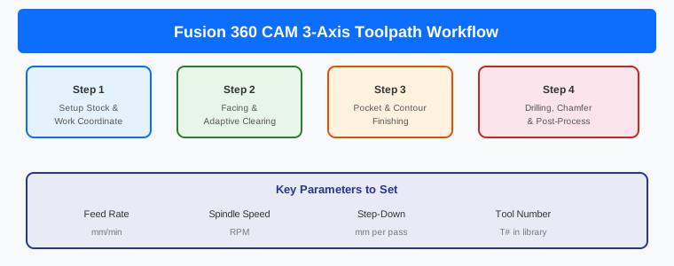
Once your CAD model is complete, switch to the Manufacture workspace. The Setup menu is the foundation — here you define stock material dimensions, set the WCS origin, select machine type, and define fixtures. Stock size, part orientation, zero location, and operation order all shape whether the route will be efficient or problematic. A strong setup makes the rest of the CAM workflow calmer and faster.
Building Your Tool Library
Your tool library should reflect what your machine can actually run predictably. Create tools for common operations: end mills for general cutting, ball nose for 3D surfaces, face mills for surfacing, drill bits for holes, chamfer mills for edge breaking, and engraving tools for text. For each tool, specify diameter, number of flutes, flute length, feed rate, spindle speed, and stepover/stepdown values. For desktop CNCs, conservative parameters are recommended with 0.1-0.05mm stock left for finishing.
Roughing Strategies: 2D Adaptive vs 2D Pocket
2D Adaptive Clearing
2D Adaptive Clearing maintains constant tool engagement by avoiding abrupt direction changes, creating smoother toolpaths that navigate corners and pockets efficiently. This results in predictable tool wear, better chip evacuation, and deeper axial cuts. Specify Optimal Load (radial engagement) and Maximum Roughing Stepdown (axial depth of cut).
2D Pocket
2D Pocket constrains cutting within a selection boundary but does not optimize for tool loading. Back-and-forth patterns can lead to sudden engagement increases in corners. Use 2D Adaptive for roughing whenever possible.
Finishing Operations
2D Contour creates toolpaths based on part outlines for clean, accurate edges. Use multiple depths to avoid full cutter engagement and specify finishing passes with smaller stepovers. For thin parts, use tabs to hold the part during final contour cutting. Facing prepares flat reference surfaces. 2D Chamfer creates beveled edges with 0.1-0.2mm width for edge breaking. Engrave creates text and artwork using pointed tools.
Simulation and Verification
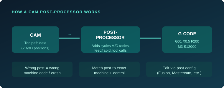
Simulation moves troubleshooting into the planning stage where correction is cheap. Check if the route clears the part correctly, tool holders are safe, time is not wasted cutting air, and operation times are reasonable. Post-processing converts CAM operations into G-code specific to your CNC controller.
Complete CAM Workflow
- Import or create CAD model
- Switch to Manufacture workspace
- Create Setup with stock, WCS, orientation, fixture
- Facing operation for flat reference surface
- 2D Adaptive Clearing roughing (leave 0.1-0.5mm)
- 2D Contour finishing
- Drilling operations with spot drill then final drill
- 2D Chamfer for edge breaking
- Simulation and collision check
- Post-process to G-code
Frequently Asked Questions
What is the best roughing strategy for beginners?
2D Adaptive Clearing is the most forgiving and efficient. It maintains constant tool engagement and produces predictable chip loads on both desktop and industrial CNCs.
How much stock should I leave for finishing?
Desktop CNCs: 0.05-0.1mm. Industrial machines: 0.2-0.5mm. Finishing at lighter stepover removes these layers for best surface finish.
How do I avoid broken tools?
Use simulation before every run. Start conservative with feeds and speeds. Leave stock for finishing rather than achieving final dimensions in roughing. Use correct tools for the material.
Sources
- Learn Fusion for CAM in 90 Minutes — Autodesk
- Basic CNC Milling: Fusion 360 CAM — UNSW
- From CAD Model to Toolpath — Pandaxis
- How To Create Toolpaths in Fusion 360