Key Takeaway: An Arduino Mega-based custom PLC delivers 24 digital inputs, 16 relay outputs, Modbus RTU communication, and ladder logic execution — all for under $40 in parts, making it a practical alternative to commercial PLCs for small automation projects.
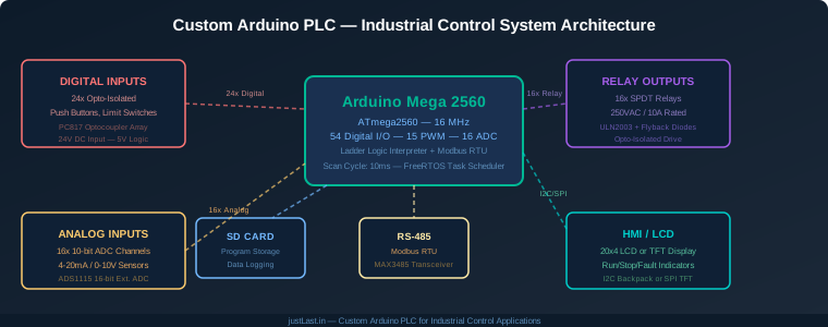
Table of Contents
- 1. Why Build a Custom PLC?
- 2. Hardware Design: Inputs, Outputs, and Isolation
- 3. Ladder Logic Interpreter on Arduino
- 4. Modbus RTU Slave Implementation
- 5. Scan Cycle and Real-Time Execution
- 6. HMI Interface and Operator Controls
- 7. Enclosure Design and DIN Rail Mounting
- 8. Limitations and When to Use Commercial PLCs
- 9. Frequently Asked Questions
1. Why Build a Custom PLC?
Commercial PLCs from Allen-Bradley, Siemens, and Mitsubishi start at $200 for a basic unit and quickly climb to $1000+ with I/O modules. For small automation projects — conveyor control, packaging machines, simple sequential processes — that cost is hard to justify when an Arduino Mega can handle the same task for a fraction of the price.
A custom Arduino PLC is not about replacing industrial-grade PLCs in safety-critical applications. It is about giving factory engineers and hobbyists a programmable logic controller for prototyping, educational purposes, and low-risk automation tasks where the cost of a commercial PLC would exceed the project budget.
The Arduino Mega 2560 is the ideal platform for custom PLC builds because of its generous I/O count: 54 digital pins, 15 PWM outputs, and 16 analog inputs. That is enough for most small automation projects without needing shift registers or I/O expander chips.
2. Hardware Design: Inputs, Outputs, and Isolation
Industrial environments demand galvanic isolation between the control logic and field wiring. A direct connection between 24VDC sensor wires and Arduino 5V pins will destroy the MCU on the first wiring mistake. The solution is optocoupler isolation on every input and relay isolation on every output.
Digital Input Circuit: Each 24VDC input passes through a PC817 optocoupler. The input side has a current-limiting resistor (4.7k for 24V) and an LED indicator. The output side pulls an Arduino digital pin LOW when the input is active. This provides 5000V isolation between field wiring and the MCU.
Relay Output Circuit: Each Arduino digital output drives a ULN2003 Darlington array through an optocoupler. The ULN2003 switches the relay coil. Each relay has a flyback diode across the coil to suppress inductive kickback. The relay contacts are SPDT rated at 250VAC/10A — sufficient for most industrial loads including contactors, solenoids, and indicator lights.
Analog Input Circuit: For 4-20mA current loop sensors, a precision 250-ohm resistor converts the current to 0-5V for the Arduino ADC. For 0-10V sensors, a resistor divider (10k/10k) scales the voltage to 0-5V. For higher precision, add an ADS1115 16-bit I2C ADC module — it provides 4 additional channels with 16-bit resolution compared to the Arduino’s 10-bit native ADC.
Power Supply: Use a 24VDC DIN-rail mount power supply (Mean Well NDR-120-24 is a good choice) to power the field side. A buck converter steps 24V down to 5V for the Arduino. Always separate the 24V field power from the 5V logic power with a fuse on each rail.
3. Ladder Logic Interpreter on Arduino
The defining feature of a PLC is its ability to execute ladder logic — the graphical programming language that electricians and maintenance technicians understand. Implementing a ladder logic interpreter on Arduino makes the custom PLC accessible to non-programmers.
A basic ladder logic interpreter stores rungs as a structured array. Each rung contains a series of contacts (inputs) and coils (outputs) connected by AND/OR logic:
struct Rung {
    uint8_t numContacts;
    Contact contacts[MAX_CONTACTS];  // Up to 8 contacts per rung
    uint8_t coilPin;                  // Output pin
    bool coilType;                    // NORMAL or LATCH
};

struct Contact {
    uint8_t pin;      // Input pin number
    bool normallyOpen; // true = NO, false = NC
    bool invert;       // true = NOT logic
};
The interpreter scans each rung left to right: evaluate all contacts in series (AND), combine parallel branches (OR), then set the coil state. Latch coils hold their state until an unlatch coil resets them — essential for motor start/stop circuits.
Store ladder logic programs on an SD card as JSON files. The Arduino reads the JSON at startup, parses the rung structure, and begins executing the scan cycle. This allows operators to modify programs by editing the JSON file on a computer — no Arduino IDE or recompilation needed.
4. Modbus RTU Slave Implementation
The custom PLC should expose its I/O state over Modbus RTU so that SCADA systems, HMI panels, or other PLCs can read and write its registers. The Arduino Mega with a MAX3485 RS-485 transceiver acts as a Modbus slave.
Map the Modbus registers as follows:
- Coils (0x0000-0x001F): Digital outputs — relay states. Write 1 to activate a relay, 0 to deactivate.
- Discrete Inputs (0x0000-0x001F): Digital inputs — sensor states. Read-only.
- Holding Registers (0x0000-0x000F): Read/write parameters — timer values, counter presets, analog thresholds.
- Input Registers (0x0000-0x000F): Read-only values — current analog readings, timer elapsed values, error codes.
Use the ArduinoModbus library (official Arduino library) for the Modbus stack. Configure the slave address via a DIP switch on the PCB — allows up to 32 PLCs on a single RS-485 bus without address conflicts.
The Modbus polling response time depends on the scan cycle. With a 10ms scan cycle and a single master polling, the PLC responds to Modbus requests within 20-30ms — fast enough for most HMI visualization and SCADA data logging applications.
5. Scan Cycle and Real-Time Execution
PLCs execute in a deterministic scan cycle: read inputs, execute logic, write outputs. The Arduino Mega implementation uses Timer1 interrupt to enforce a consistent 10ms scan cycle regardless of other code execution:
- Phase 1 — Input Scan (2ms): Read all 24 digital inputs and 16 analog channels. Store in input image table.
- Phase 2 — Logic Execution (5ms): Execute all ladder logic rungs. Update coil states in output image table.
- Phase 3 — Output Write (2ms): Write output image table to relay drivers and PWM outputs.
- Phase 4 — Communication (1ms): Process Modbus requests, update HMI display, check watchdog.
FreeRTOS manages task scheduling, but the scan cycle runs at the highest priority in a timer interrupt. This ensures the PLC logic executes every 10ms regardless of what other tasks (display refresh, Modbus communication, data logging) are running.
For applications requiring faster scan cycles (servo control, high-speed counting), reduce the cycle to 5ms by limiting the number of rungs or using direct port manipulation instead of digitalWrite for I/O.
6. HMI Interface and Operator Controls
Every PLC needs local operator controls: start/stop buttons, mode selector, status indicators, and a display showing process values. The custom Arduino PLC integrates these directly on the enclosure front panel.
Physical Controls:
- Start Button: Green momentary pushbutton — sets the RUN bit in the ladder logic
- Stop Button: Red mushroom-head E-stop — hardware interrupt, bypasses software to directly disable all outputs
- Mode Switch: 3-position selector — AUTO / OFF / MANUAL
- Run LED: Green LED — ON when PLC is executing ladder logic
- Fault LED: Red LED — flashing for warnings, solid for faults
Display: A 20×4 character LCD with I2C backpack shows current process values, active alarms, and Modbus slave address. For more complex displays, a 3.5-inch TFT with touch provides a graphical interface showing analog values as bar charts and relay states as indicators.
7. Enclosure Design and DIN Rail Mounting
Industrial PLCs mount on standard 35mm DIN rail inside NEMA-rated enclosures. The custom Arduino PLC follows the same convention for professional installation.
Enclosure Specifications:
- Size: 200mm x 120mm x 60mm (fits standard DIN rail modules)
- Material: ABS or polycarbonate, IP65 rated for washdown environments
- Mounting: DIN rail clip on the back panel, plus 4 corner screws for panel mount
- Connectors: Screw terminal blocks (2.54mm pitch) for all I/O — no soldering required for field wiring
- Cable Entry: PG9 cable glands on top and bottom for clean cable routing
The PCB mounts on standoffs inside the enclosure with the screw terminals accessible through cutouts in the front panel. The front panel also has cutouts for the LCD display, LEDs, and pushbuttons. Use a laser-cut or 3D-printed front panel overlay for a professional appearance.
8. Limitations and When to Use Commercial PLCs
The Arduino Mega PLC has real limitations that make commercial PLCs necessary for certain applications:
- No safety certification: Not suitable for E-stop circuits, light curtains, or any safety function requiring SIL or PLe rating
- Limited scan speed: 10ms minimum scan cycle vs 1ms or faster on commercial PLCs
- No redundant I/O: Single-point failure on any I/O channel — no hot-swap or redundancy
- No programming software ecosystem: No equivalent to RSLogix, TIA Portal, or GX Works for ladder logic development
- Temperature range: 0C to 70C operating range vs -40C to +85C for industrial PLCs
Use the Arduino PLC for: prototyping automation concepts, educational training, low-risk sequential control (conveyor indexing, packaging timing, simple tank level control), and hobby projects where the cost of a commercial PLC would exceed the project budget.
Use commercial PLCs for: any application involving human safety, high-speed motion control, processes requiring regulatory compliance, or systems where uptime is critical and downtime costs exceed the PLC price.
Frequently Asked Questions
How many I/O points can an Arduino Mega PLC support?
The Arduino Mega natively supports 54 digital I/O and 16 analog inputs. With shift registers (74HC595) for outputs and analog multiplexers (CD4067) for inputs, you can expand to 128+ digital I/O and 64+ analog channels. However, each expansion adds latency to the scan cycle — practical limit is around 64 I/O for a 10ms scan.
Can the Arduino PLC communicate with a Siemens S7-1200?
Yes, via Modbus RTU. The Siemens S7-1200 supports Modbus RTU as a master or slave. Configure the S7-1200 Modbus master to poll the Arduino PLC slave registers. The Arduino responds with its I/O state, and the S7-1200 can write setpoints or commands back. This works for data exchange but not for safety-critical control.
Is the ladder logic interpreter compatible with RSLogix programs?
No. The Arduino ladder logic interpreter uses a simplified rung structure that does not support all RSLogix instructions (timer-on-delay, counter-up, shift register, etc. are implemented separately). It is a subset designed for basic relay logic, not a full PLC programming environment. For complex programs, consider using Structured Text on the Arduino instead.
What is the maximum relay switching frequency?
Standard mechanical relays (SRD-05VDC-SL-C) are rated for 100,000,000 mechanical operations but should not be switched faster than 10 Hz to prevent contact welding. For higher switching frequencies (PWM-like control), use solid-state relays (SSRs) rated for the required frequency and load current.
How do I backup and restore PLC programs?
Programs are stored as JSON files on the SD card. Remove the SD card and copy the JSON file to a computer for backup. To restore, copy the JSON file back to the SD card and power-cycle the PLC. The interpreter reads the JSON at startup and begins executing the new program. Multiple programs can be stored on the SD card and selected via the mode switch.
Related Reading
- STM32 vs Arduino for Industrial Applications: Why Professionals Choose STM32
- PLC vs Industrial PC: Which Is Right for Factory Automation?
- Modbus TCP vs EtherNet/IP: Industrial Ethernet Protocols Compared
- Stepper Motor Driver Comparison: DRV8825 vs TMC2209
Sources
- Arduino Mega 2560 Official Product Page
- Modbus Organization — Protocol Specifications
- ArduinoModbus Library — Official GitHub Repository
- Mean Well DIN-Rail Power Supplies
- Arduino Shift Register Tutorial — Random Nerd Tutorials
Disclosure: This post contains affiliate links. When you purchase through these links, we may earn a small commission at no additional cost to you. This supports our content creation and helps us provide free industrial automation guides.