Key Takeaway: Understanding the four core CNC milling operations — face, slot, contour, and pocket milling — is essential for selecting the right toolpath strategy, optimizing material removal rates, and achieving precision finishes on any CNC machine.
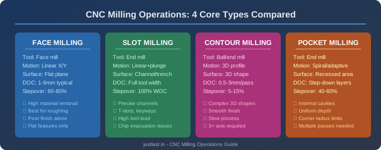
Table of Contents
1. What Is CNC Milling?
CNC milling is a subtractive manufacturing process where a computer-controlled cutting tool removes material from a workpiece to create a desired shape. Unlike turning (where the workpiece rotates), in milling the cutting tool rotates while the workpiece moves along multiple axes. This fundamental difference enables CNC milling machines to create an enormous variety of geometries — from simple flat surfaces to complex 3D contoured parts.
At its core, CNC milling involves three critical parameters: the cutting tool (end mill, face mill, or ball nose), the toolpath (the route the tool follows), and the machining parameters (spindle speed, feed rate, depth of cut). Mastering the interplay between these elements is what separates a novice machinist from an expert.
Modern CNC mills operate on 3 to 5 axes, with the most common being 3-axis (X, Y, Z), 4-axis (adds A rotation), and 5-axis (adds A and B rotation). Each additional axis dramatically expands the range of possible geometries but also increases programming complexity and machine cost.
2. Face Milling
Face milling is the most fundamental CNC milling operation. It creates a flat surface on the workpiece by moving a large-diameter cutter across the material in overlapping passes. Face mills typically have diameters ranging from 50mm to 200mm with multiple inserts (carbide or ceramic), allowing high material removal rates.
Key parameters for face milling:
- Depth of cut (DOC): 1–6mm for steel, up to 10mm for aluminum
- Stepover: 60–80% of tool diameter for optimal surface finish
- Feed rate: Depends on insert grade and material — typically 0.1–0.3mm per tooth
- Spindle speed: 2,000–8,000 RPM for steel, 8,000–20,000 RPM for aluminum
Face milling is ideal for squaring off raw stock, creating reference surfaces, and preparing workpieces for subsequent operations. The large contact area distributes cutting forces, making it a stable operation even on less rigid machines.
Pro tip: Use climb milling (tool rotates into the cut) rather than conventional milling for better surface finish and longer tool life. Most modern CNC machines are rigid enough to handle climb milling without backlash issues.
3. Slot Milling
Slot milling cuts a channel or groove into the workpiece using an end mill at full width of cut (WOC). Unlike face milling where the tool covers a wide area, slot milling engages the entire diameter of the end mill, creating precise channels for T-slots, keyways, grooves, and fluid passages.
Slot milling presents unique challenges:
- Full radial engagement: 100% WOC means maximum cutting forces — reduce feed rate accordingly
- Chip evacuation: Chips are trapped in the slot — use peck milling or through-spindle coolant
- Tool deflection: Long, thin end mills deflect under full load — use shorter tools when possible
- Heat buildup: Restricted chip flow traps heat — monitor tool temperature closely
For deep slots (depth > 3x diameter), use the trochoidal milling technique — a series of circular tool paths that maintain constant engagement angle. This reduces tool load by 40–60% compared to conventional slotting while achieving the same result.
4. Contour Milling
Contour milling creates complex 3D surfaces by following a programmed profile path. This is where CNC milling truly shines — producing organic shapes, molds, dies, and aerodynamic surfaces that would be impossible with manual machining. Contour milling typically requires ball nose end mills for smooth surface finish.
The key to quality contour milling is stepover control:
- Stepover (scallop height): 5–15% of tool diameter for finishing passes
- Scallop height formula: h = R – √(R² – (S/2)²), where R = tool radius, S = stepover
- Surface finish target: 0.8–3.2 Ra micrometers depending on application
Contour milling is computationally intensive. CAM software generates thousands of toolpath points per second, each calculated to maintain constant scallop height across the entire surface. High-performance CAM systems like Fusion 360, Mastercam, and HyperMill can generate optimized contour toolpaths in minutes.
When to use contour milling: Mold cavities, die surfaces, aerospace components, medical implants, automotive body panels, and any part requiring smooth, complex 3D geometry.
5. Pocket Milling
Pocket milling removes material from an enclosed area to create a recessed cavity with a flat bottom and defined walls. Unlike slot milling (open on both ends), pockets are bounded on all sides, requiring the tool to clear material from within the boundary.
Pocket milling strategies:
- Offset (conventional): Tool spirals inward from the boundary — simple but creates sharp corners
- Adaptive clearing: Maintains constant tool engagement angle — dramatically reduces cycle time and tool wear
- Trochoidal: Circular tool paths with progressive stepover — ideal for hard materials
- Raster: Back-and-forth直线 passes — good for flat-bottom pockets
The corner radius in a pocket is determined by the end mill radius. A 6mm end mill creates a minimum 3mm corner radius. For tighter corners, use smaller tools or add corner-relief features in the CAD model.
Depth management: Most pocket milling requires multiple Z-level passes. A common approach is roughing at 1x diameter depth per pass, followed by a finishing pass at 0.5mm to clean up the floor and walls.
6. Toolpath Strategies Compared
| Strategy | Best For | MRR | Surface Finish | Tool Life |
|---|---|---|---|---|
| Raster | Flat surfaces, roughing | High | Medium | Medium |
| Trochoidal | Deep slots, hard materials | Medium-High | Medium | Excellent |
| Adaptive | Roughing any pocket/slot | High | Low | Excellent |
| Spiral | Circular pockets, bosses | Medium | Good | Good |
| Scallop | 3D finishing, molds | Low | Excellent | Medium |
7. How to Select the Right Operation
Choosing the correct CNC milling operation depends on four factors: part geometry, material, surface finish requirements, and production volume. Here is a practical decision framework:
For flat surfaces: Start with face milling for roughing, then switch to a smaller end mill with raster finishing for final surface quality. This two-step approach balances speed with precision.
For channels and grooves: Use slot milling for simple straight channels. For T-slots or keyways, use the appropriate slot mill geometry. If the slot is deeper than 3x the tool diameter, switch to trochoidal milling.
For 3D surfaces: Contour milling is your only option. Use a ball nose end mill for smooth surfaces, and choose stepover based on your surface finish requirement. For roughing complex 3D shapes, use adaptive clearing with a flat end mill to remove bulk material quickly.
For internal cavities: Pocket milling with adaptive clearing is the most efficient approach. Set your stepover to 40–60% for roughing, then finish with a light pass at full depth.
Frequently Asked Questions
What is the difference between face milling and end milling?
Face milling uses a large-diameter cutter (50mm+) with inserts to create flat surfaces. End milling uses smaller-diameter tools (3–25mm) with flutes along the cutting edge for slots, pockets, and contours. Face mills are for surface area; end mills are for detail work.
How do I choose between climb and conventional milling?
Use climb milling (tool rotation into the cut direction) for most CNC work — it produces better surface finish, reduces tool deflection, and extends tool life. Use conventional milling only on very old or loose machines where backlash could cause the workpiece to be pulled into the cutter.
What is trochoidal milling and when should I use it?
Trochoidal milling uses circular tool motions with progressive lateral stepover. It maintains a constant engagement angle, reducing tool load by 40–60%. Use it for deep slots, hard materials (stainless steel, titanium), and situations where tool breakage is a concern.
Can I mill aluminum on a standard 3-axis CNC router?
Yes, but with limitations. Aluminum requires higher spindle speeds (8,000–20,000 RPM) and proper chip evacuation. Use single-flute end mills, apply cutting fluid, and reduce feed rates compared to recommended values for a rigid VMC. Expect slower cycle times but achievable results.
Related Reading
- CNC End Mills: Complete Guide to Types, Materials and Selection
- Feeds and Speeds for CNC: Complete Calculation Guide
- Fusion 360 CAM for CNC: Complete Toolpath Guide
- G-Code Programming Fundamentals for CNC Beginners
- CNC Machine Calibration: Step-by-Step Accuracy Setup
Sources
- CNC Cookbook — CNC Milling Operations Overview
- Harvey Performance — Milling Operations Guide
- Autodesk Fusion 360 — CNC Milling Toolpath Strategies
- Practical Machinist — Trochoidal Milling Discussion
Disclosure: This post contains affiliate links. If you purchase through these links, we may earn a commission at no additional cost to you. This helps support our content creation.