Key Takeaway: Fusion 360’s integrated CAM workspace gives machinists a complete simulation-to-g-code pipeline for 3-axis milling — and mastering its core toolpaths transforms how you go from CAD model to finished part.
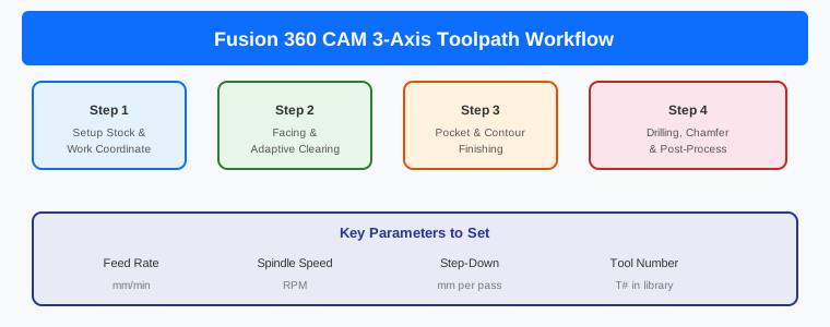
Table of Contents
- Why Fusion 360 for CNC CAM?
- Setting Up Your CAM Workspace
- Stock Setup and Work Coordinate System
- Facing Toolpath
- Adaptive Clearing (Roughing)
- Contour and Finishing Toolpaths
- Drilling Toolpaths
- Toolpath Simulation and Verification
- Post-Processing for G-Code
- Pro Tips for Better CAM Results
- Frequently Asked Questions
- Related Reading
- Sources
Three-axis CNC milling is the backbone of prototyping and small-batch production for shops like ours. Whether you are machining aluminium enclosures for linear actuators, bracketry for servo mounts, or custom fixtures for conveyor assemblies, the CAM software you choose determines how fast and how accurately those parts come off the machine. Fusion 360 CAM has become the go-to choice for small shops because it bundles CAD, CAM, simulation, and post-processing into a single environment — and it is free for startups and hobbyists under Autodesk’s personal use license.
This guide walks through every step of building a fusion 360 cam toolpath workflow for 3-axis milling, from stock setup to G-code output. Each section covers the specific settings that matter, the common mistakes beginners make, and the adjustments that separate a rough prototype from a production-ready part.
Why Fusion 360 for CNC CAM?
Fusion 360’s CAM workspace (now called the Manufacturing workspace) has several advantages over standalone CAM packages for small to mid-size shops:
- Integrated design-to-manufacturing pipeline — You model the part, define toolpaths, simulate, and post-process without ever leaving the application. No file translation errors between CAD and CAM software.
- Cloud-based collaboration — Team members can review and comment on toolpath setups from any browser, which is useful when your design engineer and machinist are in different rooms of the factory.
- Built-in tool library — Store your actual cutting tools with flute count, coating type, stickout length, and recommended feeds and speeds. Once configured, you reuse them across every project.
- Free for startups and personal use — Autodesk offers a 3-year startup license and a personal use license at no cost. For a small shop, this eliminates the per-seat cost of Mastercam or Fusion 360’s own commercial tier.
- Generative adaptive clearing — Fusion 360’s adaptive roughing algorithm is among the best in the industry, maintaining constant tool engagement angle to extend tool life and reduce cycle time.
For shops transitioning from manual G-code writing or basic CAM tools, Fusion 360 represents a significant leap in capability without a significant leap in cost.
Setting Up Your CAM Workspace
When you first open the Manufacturing workspace, Fusion 360 presents a toolbar organised by workflow stage: Setup, Milling, Drilling, Turning, and Cutting. For 3-axis milling, you will primarily work in the Milling section. Here is the recommended order of operations:
- Create a Setup — Defines the stock material, work origin, and machining axis orientation.
- Add a Facing operation — Cleans the top surface to establish a reference Z-height.
- Add Adaptive Clearing — Removes the bulk of the material efficiently.
- Add Contour or Parallel finishing — Brings surfaces to final dimension and surface finish.
- Add Drilling (if needed) — Holes, peck cycles, or tapping.
- Simulate — Verify there are no collisions or gouges.
- Post-process — Generate G-code for your specific controller.
Each operation builds on the previous one’s stock model. Fusion 360 tracks remaining material automatically, so your finishing passes only remove what the roughing passes left behind.
Stock Setup and Work Coordinate System
The Setup dialog is where you define everything the CAM engine needs before any toolpath is calculated. Getting this wrong means wasted material and potential machine damage.
Stock Definition
Fusion 360 offers several stock modes:
- Fixed size box — You specify exact dimensions (Length × Width × Height). Use this when you know your raw material size precisely, such as a standard 100 × 100 × 25 mm aluminium billet.
- Relative size box — Adds a uniform offset around the model. Useful when the stock is oversized on all sides.
- From solid — Use an existing body as the stock model. Handy for second-operation setups where the stock is a partially machined part.
- Cylinder — For round bar stock being machined on a mill.
Work Coordinate System (WCS)
The WCS origin should match exactly where you set your G54 (or G55/G56) work offset on the actual machine. Common choices:
- Top-center of stock — Easiest to set with an edge finder or probe. X0 Y0 at the center, Z0 at the top surface.
- Corner of stock — X0 Y0 at a corner, Z0 at the top. Requires careful stock trimming so the corner is clean.
- Part origin — X0 Y0 Z0 at the model’s design origin. Best when the model origin aligns with a datumbore on the physical part.
For 3-axis milling, always align the Z-axis with the spindle axis. The Y-axis should point into the column (away from the operator), and X should be the long travel on a standard mill. This convention matches most post-processors’ expectations.
Facing Toolpath
A facing pass flattens the top of the stock to your target Z-height. Even if the stock looks flat, always run a facing operation as your first pass — it establishes a known reference surface and removes any mill scale or surface oxidation.
Key Settings
- Tool: Use a face mill or a large-diameter end mill (e.g., 50 mm face mill or 20 mm flat end mill for smaller parts).
- Pattern: “One Way” gives the best surface finish. “Zig Zag” is faster but may leave witness marks at direction changes.
- Stepover: Set to 60-80% of the tool diameter for face mills. Going beyond 80% risks leaving ridges.
- Allowance: Set to 0 for a finished facing pass, or leave 0.1-0.2 mm if you plan to finish later.
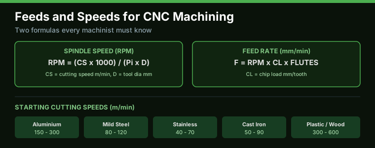
Feed rate for facing aluminium with a 50 mm face mill at 10,000 RPM typically runs 800-1200 mm/min. Start conservative and increase once you confirm the surface finish is acceptable.
Adaptive Clearing (Roughing)
Adaptive Clearing is Fusion 360’s signature roughing strategy and the reason many machinists switched from other CAM platforms. Unlike traditional offset roughing, adaptive clearing maintains a constant engagement angle between the tool and the material. This means:
- The tool never buries itself in a corner at full width of cut.
- Spindle load stays consistent, preventing tool breakage on small machines.
- You can cut at full depth of cut with a smaller stepover, which is actually faster than shallow passes at full stepover.
Critical Settings
- Optimal Load (Stepover): For a 10 mm end mill in 6061 aluminium, start at 1.5-2.0 mm (15-20% of diameter). For harder materials like stainless, reduce to 10-15%.
- Maximum Roughing Stepdown: Set to 1× diameter or up to 2× for peripheral cutting in aluminium. Your machine rigidity is the limiting factor here.
- Stock to Leave: Leave 0.2-0.3 mm on walls and floors for a finishing pass to clean up.
- Finishing Passes: Enable “Additional Finishing Passes” to add a spring pass on walls and floors, which improves dimensional accuracy.
- Ramp Style: “Helical” ramping is the safest entry method. “Plunge” is fastest but stresses the tool. “Profile” ramping follows the part contour downward.
A well-tuned adaptive clearing setup for a 50 × 50 × 20 mm aluminium block with a 10 mm end mill can clear the bulk of material in under 5 minutes on a rigid machine. Compare that to 15-20 minutes with traditional offset roughing — the cycle time reduction alone justifies learning this toolpath.
Contour and Finishing Toolpaths
After adaptive clearing, you have a part that is close to final dimensions but with visible scallops and a rough surface finish. Finishing toolpaths bring everything to spec.
2D Contour
The 2D Contour toolpath follows a selected chain at a constant Z-depth. Use it for vertical walls, profiles, and step-down features. Set the stock-to-leave to zero and enable a finishing pass with a small stepover (0.1-0.2 mm) for a clean wall finish.
3D Parallel
For curved or organic surfaces, the Parallel toolpath rasterises across the surface in linear passes. Control surface finish with the stepover — for a 6 mm ball nose end mill, a 0.2 mm stepover produces a surface roughness (Ra) of approximately 0.8 µm in aluminium.
3D Scallop
The Scallop toolpath is superior to Parallel for surfaces with varying slopes because it maintains consistent scallop height across the entire surface regardless of slope angle. Use it when surface finish uniformity matters — like cosmetic surfaces on enclosure covers.
Rest Machining
Enable rest machining on finishing passes so the tool only cuts where the previous operation could not reach. This prevents air cutting and reduces cycle time significantly on parts with complex geometry.
Drilling Toolpaths
Fusion 360’s drilling operations support standard cycles directly from the CAM interface. Key cycles for 3-axis milling:
- Drilling (G81) — Simple through-hole or blind-hole drilling. Specify tip angle (typically 118° or 135°) and breakthrough depth.
- Peck Drilling (G83) — Retracts the tool periodically to clear chips. Essential for deep holes (depth > 3× diameter). Set the peck depth to 1-2× diameter depending on material.
- Tapping (G84) — For cutting threads. Match the TPI exactly to your tap — Fusion 360 calculates the feed rate automatically from spindle RPM and thread pitch.
- Boring (G85/G89) — For enlarging existing holes to precise diameters.
Always set the clearance plane high enough to clear any clamps or fixtures. A 5 mm clearance plane above the part is typical, but verify with simulation if your setup has tall workholding.
Toolpath Simulation and Verification
Before posting G-code, run the full simulation. Fusion 360’s simulator shows:
- Material removal animation — Watch the tool cut through the stock in real time. Check for unexpected gouges or untouched areas.
- Gouge and collision detection — Enable this to get automatic warnings when the tool holder, shank, or spindle hits the part or fixtures.
- Stock comparison — Compare the simulated result against the target model. Areas in red are excess material; areas in blue are overcuts.
- Toolpath statistics — Total cycle time, maximum spindle load, feed rate, and tool changes.
A 5-minute simulation run can save you hours of machine time and hundreds of dollars in broken tools. Never skip simulation, especially on a new toolpath or when machining expensive material.
Post-Processing for G-Code
The post-processor converts Fusion 360’s internal toolpath data into G-code that your specific CNC controller understands. This is where many beginners get stuck.
Selecting the Right Post-Processor
Fusion 360 ships with hundreds of post-processors. Common ones for small shops:
- Fusion 360 Generic — Basic G-code output. Works with most GRBL, LinuxCNC, and Mach3 controllers.
- Haas (Next Generation) — For Haas mills. Includes probing cycles and tool length offsets specific to Haas controls.
- Siemens 840D — For Siemens-based controllers. Outputs in ShopTurn or G-code format.
- Fanuc — The most widely supported post in the industry. Covers most Fanuc-controlled mills.
You can find additional post-processors on the Autodesk CAM Post Library or create custom ones using the Autodesk HSM Post Processor configuration files (XML-based).
Post-Processing Checklist
- Verify the output format matches your controller (G-code vs. Conversational).
- Check that tool change commands (M06 Txx) use the correct pocket numbering.
- Confirm coolant commands (M08/M09) are present if your machine requires them.
- Look for G28 or G30 return-to-home commands at the end of the program.
- Verify the feed rate units (mm/min vs. in/min) match your machine settings.
Pro Tips for Better CAM Results
These tips come from real-world machining experience and will save you time and material:
- Use templates. Once you have a toolpath setup that works for a material and tool combination, save it as a template. Apply it to new projects with one click.
- Check tool stickout. If the tool sticks out more than 4× its diameter, you will get chatter. Reduce the stepover or increase the feed rate to compensate.
- Coolant matters. Flood coolant for aluminium roughing, mist or air blast for finishing. Dry machining in steel causes rapid tool wear.
- Workholding in CAM. Model your clamps and vise in the setup so the simulation can detect collisions. This is the single most common cause of machine crashes.
- Organise operations by tool. Group all operations using the same tool together to minimise tool changes. Fusion 360’s “Reorder Operations” feature handles this automatically.
- Use machine ink (machine awareness). Fusion 360 supports machine definitions that enforce travel limits, maximum feed rates, and rapid rates specific to your CNC. Set this up once and let the software prevent out-of-range moves.
Frequently Asked Questions
What is the best fusion 360 cam toolpath for roughing aluminium?
Adaptive Clearing is the best roughing toolpath in Fusion 360 for aluminium. It maintains constant tool engagement, reducing heat buildup and tool deflection. Set the optimal load to 15-20% of tool diameter, use helical ramping, and cut at full depth of cut with a reduced stepover. This strategy removes material faster than traditional offset roughing while extending tool life significantly.
How do I reduce cycle time with fusion 360 cam toolpath settings?
Reduce cycle time by optimising three key areas: increase the optimal load in adaptive clearing (within your machine’s capability), enable multiple depths per pass, and use rest machining on finishing passes to avoid air cutting. Also, organise operations by tool to eliminate unnecessary tool changes, and use high-efficiency milling (HEM) parameters where your machine rigidity allows it.
Can I use fusion 360 cam for 5-axis machining?
Yes, Fusion 360 supports 5-axis machining through its paid commercial license. The 5-axis workflows include simultaneous 5-axis toolpaths, 3+2 positional machining, and multi-axis trimming. However, the free personal use license is limited to 2-axis turning and 3-axis milling. For a small shop doing mostly 3-axis work, the personal license covers most needs.
How do I post-process G-code for my specific CNC machine?
In the Fusion 360 Manufacturing workspace, click the “Post Process” button and select your machine’s post-processor from the library. If your exact machine is not listed, search the Autodesk CAM Post Library online or use a compatible generic post (such as “Generic Fanuc” for most Fanuc-controlled mills). Custom post-processors can be edited using the HSM Post Processor XML configuration files.
Related Reading
- CNC Machine Calibration: Complete Guide to Squaring, Tramming, and Backlash Compensation — Ensure your machine is properly calibrated before running any CAM-generated toolpaths.
- CNC End Mills and Tooling: Complete Guide to Flute Count, Coatings, and Feeds — Choose the right cutting tools for the Fusion 360 CAM toolpaths described in this guide.
Sources
- Autodesk Fusion 360 Manufacturing Workspace Documentation — Official Autodesk help documentation for CAM setup and toolpath configuration.
- CNCCookbook: Fusion 360 CAM CNC Tutorial — Practical tutorial covering Fusion 360 CAM basics and workflow tips.
- CNCCookbook: High Efficiency Milling (HEM) Guide — Understanding adaptive clearing strategies and HEM parameters.
- Autodesk CAM Post Library — Download post-processors for hundreds of CNC controllers.
Affiliate Disclosure: justLast.in is reader-supported. Some links in this article may be affiliate links. If you purchase through these links, we may earn a small commission at no additional cost to you. We only recommend products and tools we have personally used or thoroughly evaluated in our workshop.