Key Takeaway: Building a custom HMI touchscreen interface with an STM32F4 microcontroller gives factory engineers full control over machine visualization, real-time sensor monitoring, and PLC communication — at a fraction of commercial HMI panel costs.
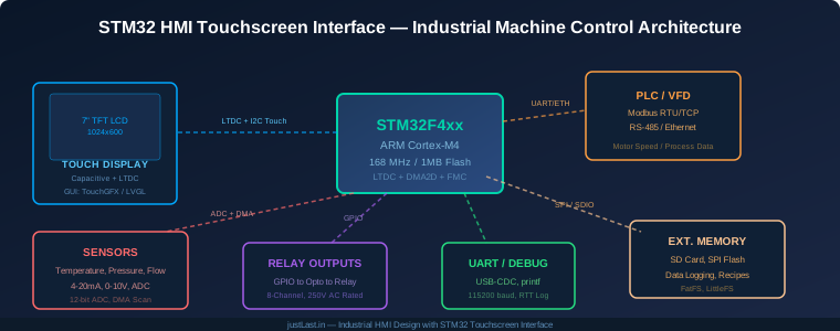
Table of Contents
- 1. Why STM32 for Industrial HMI?
- 2. Hardware Architecture and Component Selection
- 3. Display and Touch Interface Implementation
- 4. GUI Framework: TouchGFX vs LVGL
- 5. Modbus Communication with PLC and VFD
- 6. Sensor Data Acquisition and Processing
- 7. Relay Output Control and Safety
- 8. Data Logging and Recipe Management
- 9. Real-World Project: CNC Coolant HMI Panel
- 10. Frequently Asked Questions
1. Why STM32 for Industrial HMI?
Commercial HMI panels from Siemens, Weintek, and Proface cost anywhere from $300 to $2000 depending on screen size and features. For factory owners running small to medium production lines, that per-machine cost adds up fast. An STM32-based custom HMI gives you the same touchscreen visualization, Modbus communication, and real-time sensor monitoring at under $50 in components.
The STM32F4 series — particularly the STM32F407 and STM32F429 — is the sweet spot for industrial HMI projects. Here is why these chips dominate the custom HMI space:
- LTDC (LCD-TFT Display Controller): Built-in parallel RGB interface drives TFT displays up to 800×480 without external controllers. The STM32F429 adds a Chrom-ART accelerator (DMA2D) for hardware-accelerated graphics blending.
- Cortex-M4 with FPU: 168 MHz clock speed with single-precision floating point handles sensor math, PID calculations, and Modbus CRC computation in real time.
- Multiple UART/SPI/I2C peripherals: Connect to PLC via Modbus RTU on one UART, read sensors on I2C/SPI, and debug on USB-CDC — all simultaneously.
- 1 MB internal flash: Enough for TouchGFX or LVGL firmware, GUI assets, Modbus stack, and application logic without external memory.
- DMA engine: Offload display refresh, ADC scanning, and UART transfers from the CPU — critical for maintaining sub-100ms touch response times.
For factory floor deployment, the STM32 operates at 3.3V logic with industrial temperature range options (-40C to +105C), making it suitable for environments where commercial HMI panels sometimes fail.
2. Hardware Architecture and Component Selection
A complete STM32 HMI system requires five functional blocks working together. Here is the recommended component selection for each:
Microcontroller: STM32F407VGT6 (LQFP100) or STM32F429ZIT6 (LQFP144). The 407 handles most HMI applications. Choose the 429 if you need the Chrom-ART accelerator for smooth animations on larger displays.
Display Module: 7-inch TFT with capacitive touch panel (CTP). Recommended modules: ER-TFTM070-3 with ILI9806 controller, or the more common AT070TN94 with FT5x06 touch controller. Both provide 1024×600 resolution with I2C capacitive touch.
Communication Interface: For Modbus RTU, use MAX3485 RS-485 transceiver connected to USART1 or USART2. For Modbus TCP, add a W5500 Ethernet module connected via SPI. The W5500 handles TCP/IP stack in hardware, freeing the STM32 for application code.
Sensor Input: Use the onboard 12-bit ADC with DMA for analog sensors (4-20mA via 250-ohm resistor, or 0-10V via resistor divider). For digital sensors, I2C or SPI interfaces read temperature (MAX31865), pressure (HX711 or ADS1256), and flow sensors directly.
Relay Outputs: Optocoupler-isolated relay modules (SRD-05VDC-SL-C) driven from GPIO through ULN2003 driver ICs. Always use flyback diodes and opto-isolation — never drive relays directly from STM32 pins in an industrial environment.
3. Display and Touch Interface Implementation
The display connection uses the STM32 LTDC peripheral in parallel RGB mode. The wiring is straightforward:
- Data lines: 16-bit RGB565 (R[4:0], G[5:0], B[4:0]) mapped to GPIO pins per the LTDC pinout table in the reference manual
- Control signals: HSYNC, VSYNC, CLK, DE connected to the display module header
- Backlight: PWM-controlled via TIM3 channel 3 through a MOSFET for brightness adjustment
- Touch (I2C): FT5x06 capacitive touch controller on I2C1 (PB6-SCL, PB7-SDA) with interrupt on PB5
The LTDC initialization in CubeMX requires setting the pixel clock to match the display timing requirements. For a 1024×600 display at 60fps refresh, the pixel clock should be approximately 51.2 MHz. Configure the LTDC layer with RGB565 pixel format and set the framebuffer address to a 1024x600x2 = 1.2 MB SRAM buffer.
Touch coordinate mapping is critical for accurate HMI interaction. The FT5x06 reports raw touch coordinates in its own coordinate space. You must calibrate these to match the LCD pixel coordinates using a 4-point or 9-point calibration routine stored in flash.
4. GUI Framework: TouchGFX vs LVGL
Two GUI frameworks dominate the STM32 HMI space. Your choice depends on licensing, features, and display size:
TouchGFX (ST Microelectronics): Free for STM32 MCU designs. Provides a visual designer tool (TouchGFX Designer) with drag-and-drop widget placement. Hardware-accelerated via DMA2D on F429. Excellent for simple gauges, buttons, and status displays. Limitation: closed-source runtime, proprietary asset pipeline.
LVGL (Light and Versatile Graphics Library): Open-source under MIT license. Works on any MCU, not just STM32. More widget variety (charts, sliders, keyboards, animations). Active community with 15,000+ GitHub stars. Slightly higher CPU usage than TouchGFX due to software rendering, but still fast enough for 60fps on Cortex-M4.
For industrial HMI projects, LVGL is the recommended choice for three reasons: MIT license allows commercial use without restrictions, the open-source nature means you can debug and customize every rendering path, and the widget library includes industrial-specific elements like bar gauges, arc meters, and chart widgets that TouchGFX lacks.
A typical LVGL setup for STM32 uses FreeRTOS with a dedicated GUI task running at priority 3. The touch interrupt triggers a lv_indev_read callback that feeds coordinates to the LVGL input driver. Display refresh uses double-buffering: one framebuffer rendered by LVGL while the other is being sent to the display by LTDC DMA.
5. Modbus Communication with PLC and VFD
Most factory floor devices communicate via Modbus RTU (RS-485) or Modbus TCP (Ethernet). Your STM32 HMI needs to act as a Modbus master, reading registers from PLCs and writing speed commands to VFDs.
For Modbus RTU implementation, the libmodbus library ports cleanly to STM32. Configure USART1 at 9600 or 19200 baud with 8N1 framing. The MAX3485 transceiver requires a direction pin (GPIO) to switch between transmit and receive modes — use an idle-timeout timer to automatically switch back to receive after transmission completes.
Key Modbus registers to read from a typical PLC:
- Coils (0x): Digital outputs — machine running, fault active, door open/closed
- Discrete Inputs (1x): Digital inputs — start button, stop button, limit switches
- Input Registers (3x): Read-only analog values — temperature, pressure, motor current
- Holding Registers (4x): Read/write values — setpoint temperature, motor speed, recipe parameters
For VFD speed control, write the target frequency (scaled to 0.1 Hz resolution) to holding register 0x0001 while maintaining the run command on coil 0x0000. Always implement a heartbeat watchdog — if the HMI stops writing to the VFD for more than 3 seconds, the VFD should auto-stop for safety.
6. Sensor Data Acquisition and Processing
The STM32 ADC with DMA provides continuous sensor sampling without CPU intervention. Configure the ADC in scan mode with DMA circular buffer to sample multiple analog channels in sequence:
- Channel 0: Temperature sensor (PT100 via MAX31865, or 4-20mA loop)
- Channel 1: Pressure transducer (0-10V scaled to 0-100 bar)
- Channel 2: Flow meter pulse input (external counter, not ADC)
- Channel 3: Motor current sense (hall-effect sensor output)
Apply a software low-pass filter (exponential moving average, alpha = 0.1) to smooth ADC readings before displaying on the HMI. For temperature sensors, add cold-junction compensation if using thermocouples, or use the built-in reference voltage calibration for PT100 RTD sensors.
Sampling rate matters: 1 kHz is sufficient for most industrial process variables. Set the ADC prescaler to /8 for 10.5 MHz ADC clock, giving 12-bit conversion in 1 microsecond per channel. With 4 channels, a full scan completes in 4 microseconds — far faster than any industrial process variable changes.
7. Relay Output Control and Safety
Industrial relay control requires isolation, debouncing, and fail-safe defaults. Never connect STM32 GPIO pins directly to relay coils — the inductive kickback will destroy the MCU.
The safe relay drive circuit: GPIO pin connects to an optocoupler (4N25 or PC817) input through a current-limiting resistor. The optocoupler output drives a ULN2003 Darlington array, which switches the relay coil. The relay contacts are rated for your load voltage (typically 250VAC/30A for industrial contactors).
Implement these safety measures in firmware:
- Power-on default: All relay outputs OFF (GPIO low). Machine does not start unexpectedly after power restoration.
- Watchdog timeout: If the main loop hangs, the independent watchdog (IWDG) resets the MCU, defaulting relays to OFF.
- Emergency stop: Dedicated hardware interrupt on a GPIO pin connected to the E-stop circuit. ISR immediately disables all outputs within 10 microseconds — faster than any software polling loop.
- Output verification: Read back relay state through optocoupler feedback to confirm the relay actually switched. Detect welded relay contacts.
8. Data Logging and Recipe Management
An industrial HMI without data logging is a blind machine operator. The STM32 logs sensor readings, alarm events, and production counts to either SD card (via FatFS) or SPI flash (via LittleFS).
For SD card logging, use the SDIO interface (not SPI) for maximum throughput. A typical log entry structure:
typedef struct {
    uint32_t timestamp;    // Unix timestamp from RTC
    uint16_t temperature;  // 0.1C resolution
    uint16_t pressure;     // 0.1 bar resolution
    uint16_t motor_speed;  // RPM
    uint8_t  relay_state;  // Bitmask of relay states
    uint8_t  alarm_flags;  // Active alarm bitmask
} __attribute__((packed)) log_entry_t;  // 12 bytes per entry
At 1 sample per second, each log entry takes 12 bytes. A 16 GB SD card stores approximately 44 years of continuous data — more than enough for any industrial application.
Recipe management allows operators to save and recall machine parameters (speed, temperature, timing) for different product runs. Store recipes as JSON files on the SD card, loaded into RAM at startup. The HMI provides a recipe selection screen with save, load, edit, and delete operations.
9. Real-World Project: CNC Coolant HMI Panel
Here is a practical application: replacing a failed $800 Weintek HMI on a CNC milling machine coolant control system with a custom STM32 panel.
Requirements:
- Display coolant temperature, pressure, and flow rate in real time
- Allow operator to set temperature target (18-25C) and pressure limits
- Modbus RTU communication with the existing Allen-Bradley PLC
- Alarm display with audible buzzer for out-of-range conditions
- Data logging for quality control records
Component cost: STM32F407 Discovery board ($20) + 7-inch TFT with touch ($35) + MAX3485 module ($2) + W5500 Ethernet module ($8) + relay module ($5) + SD card breakout ($3) = $73 total. That is 90% savings compared to the original Weintek panel.
Development time: Approximately 2 weeks for a competent embedded developer, including LVGL GUI design, Modbus integration, and enclosure fabrication. The long-term savings make this approach viable for any factory running multiple machines with identical HMI requirements.
Frequently Asked Questions
Can an STM32 HMI replace commercial panels in safety-critical applications?
STM32-based HMIs can be used in non-safety-critical visualization and monitoring roles. For SIL-rated or PLe safety functions, you need certified safety controllers (such as Pilz or sick safety PLCs) with redundant I/O. The STM32 HMI works well as a visualization layer on top of certified safety systems — reading status from a safety PLC via Modbus without being part of the safety chain itself.
What display sizes work with the STM32 LTDC?
The LTDC supports parallel RGB interfaces with resolutions up to 800×480 on the STM32F407 and up to 1024×600 on the STM32F429 (with Chrom-ART). For larger displays (10.1 inch and above), you need an HDMI or LVDS bridge chip, which adds complexity and cost. The 7-inch 1024×600 sweet spot covers most industrial HMI use cases.
How reliable is an STM32 HMI compared to commercial panels?
The STM32 itself has excellent reliability — rated for 100,000 write cycles on flash and operating from -40C to +105C. The weak points are the same as commercial panels: the TFT display backlight (50,000 hours typical) and the touch panel (capacitive panels last longer than resistive). Use industrial-grade display modules rated for 24/7 operation and provide adequate ventilation in the enclosure.
Can I connect multiple VFDs to one STM32 HMI?
Yes. Modbus RTU supports up to 32 devices on a single RS-485 bus (with repeaters, up to 247). Each VFD gets a unique slave address (1-247). The STM32 polls each VFD sequentially — with 4 VFDs at 9600 baud, a complete poll cycle takes approximately 200ms, which is fast enough for HMI display refresh.
What programming language do I need for STM32 HMI development?
C is the standard language for STM32 development. LVGL and TouchGFX are both written in C, and the HAL/LL drivers from ST are C-based. You can use C++ for application logic, but the GUI framework and hardware drivers remain C. For rapid prototyping, STM32CubeIDE provides a free development environment with integrated debugger support.
Related Reading
- STM32 vs Arduino for Industrial Applications: Why Professionals Choose STM32
- Modbus TCP vs EtherNet/IP: Industrial Ethernet Protocols Compared
- I2C Communication Guide for Embedded Systems
- Edge Computing in Manufacturing: Real-Time Data Processing at the Factory Floor
Sources
- STMicroelectronics STM32F4 Series Product Page
- LVGL Documentation — Light and Versatile Graphics Library
- TouchGFX by ST Microelectronics
- Modbus Organization — Official Protocol Specifications
- FatFS File System for Embedded Applications
Disclosure: This post contains affiliate links. When you purchase through these links, we may earn a small commission at no additional cost to you. This supports our content creation and helps us provide free industrial automation guides.