Key Takeaway: STM32 microcontrollers offer an optimal balance of processing power, ADC precision, and peripheral integration for building industrial-grade sensor data acquisition systems. With 16-bit ADCs, DMA controllers, and ARM Cortex-M7 processing at 480 MHz, the STM32H7 series can handle multi-channel synchronous sampling for precision factory automation applications in 2026.
📖 Table of Contents
- 1Why STM32 Leads Industrial IoT Data Acquisition in 2026
- 2System Architecture: From Sensor to Cloud
- 3High-Precision ADC Configuration and DMA-Driven Sampling
- 4Industrial Communication Protocols: Modbus, CAN FD, and MQTT
- 5Sensor Calibration Techniques for Industrial Accuracy
- 6Implementation Guide: Building a Production Data Logger
- 7STM32 Series Comparison for Data Acquisition
- 8Frequently Asked Questions
1. Why STM32 Leads Industrial IoT Data Acquisition in 2026
Industrial IoT (IIoT) sensor data acquisition demands precision, low latency, and robust communication. In 2026, the STM32 family from STMicroelectronics has become the dominant microcontroller platform for this role, powering everything from simple temperature monitoring to multi-axis vibration analysis on factory floors.
The STM32H7 series, built around the ARM Cortex-M7 core running at up to 480 MHz, provides the computational headroom for real-time digital signal processing (DSP) without requiring an external FPGA or DSP co-processor. Its dual-bank Flash memory and large SRAM (up to 1 MB) enable sophisticated data buffering and on-device analytics.
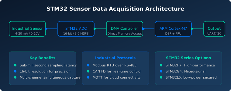
What makes STM32 particularly attractive for industrial applications is its rich peripheral set. Three 16-bit ADCs with up to 36 channels can sample simultaneously at up to 3.6 MSPS. Combined with the DMA controller, this enables glitch-free data capture even while the CPU executes application code. For factory automation in 2026, this means one STM32 chip can replace a rack of discrete signal-conditioning modules.
2. System Architecture: From Sensor to Cloud
A complete STM32-based data acquisition system follows a well-defined signal chain. Industrial sensors output 4-20 mA current loops or 0-10 V voltage signals. These enter the STM32 through its analog front-end, where internal ADCs convert them to digital values at programmer-defined sampling rates.
The DMA controller transfers completed ADC conversions directly to memory without CPU intervention. This is critical for high-channel-count applications — the CPU remains free to run control algorithms, communication stacks, and data validation while the hardware handles the repetitive sampling task.
For factory automation in 2026, a typical architecture includes:
Sensor Interface Layer: External signal conditioning (amplifiers, filters) feeding into STM32 ADC pins. The STM32G4 series includes built-in operational amplifiers and comparators, reducing external component count.
Processing Layer: The ARM Cortex-M7 or M4 core applies DSP filters (FIR, IIR), performs FFT analysis for vibration monitoring, and executes calibration algorithms. The FPU handles floating-point math in hardware for faster computation.
Communication Layer: Processed data transmits over Modbus RTU (RS-485), CAN FD, or Ethernet. For IIoT connectivity, an ESP32 companion or STM32MP1 MPU handles MQTT/HTTP uplink to cloud platforms like AWS IoT or Azure IoT Hub.
3. High-Precision ADC Configuration and DMA-Driven Sampling
The STM32 ADC subsystem is where the platform truly excels for precision measurement. Key configuration parameters include resolution (8, 10, 12, 14, or 16 bits), sampling time, and conversion mode. For industrial applications, 14-bit or 16-bit resolution is typical.
DMA-based sampling works by configuring a timer to trigger ADC conversions at precise intervals. The ADC’s data register connects directly to a DMA channel, which writes conversions into a circular buffer in SRAM. This buffer can hold thousands of samples before requiring CPU intervention.
Sample code for double-buffer DMA ADC on STM32H7:
// Configure ADC3 for continuous DMA
ADC3->CFGR |= ADC_CFGR_CONT;        // Continuous conversion mode
ADC3->CFGR |= ADC_CFGR_DMAEN;       // Enable DMA requests
ADC3->DMAADDR = (uint32_t)&adc_buffer;   // DMA target address

// Configure DMA for double-buffer transfer (ping-pong)
DMA1_Stream0->CR |= DMA_SxCR_CIRC;  // Circular mode
DMA1_Stream0->NDTR = BUFFER_SIZE;   // Number of transfers
DMA1_Stream0->PAR = (uint32_t)&ADC3->DR;  // Peripheral address
DMA1_Stream0->M0AR = (uint32_t)ping_buffer;  // Ping buffer
DMA1_Stream0->M1AR = (uint32_t)pong_buffer;  // Pong buffer
This double-buffer (ping-pong) approach ensures the CPU always has one complete buffer to process while the ADC fills the other — achieving zero sample loss at full ADC speed.
4. Industrial Communication Protocols: Modbus, CAN FD, and MQTT
An STM32 data acquisition system must communicate with PLCs, SCADA systems, and cloud platforms. Three protocols dominate in 2026:
Modbus RTU over RS-485 remains the most widely supported protocol in factory environments. STM32’s USART peripherals with RS-485 transceivers handle Modbus frames efficiently. The STM32Cube HAL includes Modbus example code for rapid development. Maximum cable length of 1200 meters makes it ideal for distributed sensor networks.
CAN FD (Flexible Data-Rate) provides higher throughput than classic CAN — up to 8 Mbps with 64-byte data frames. STM32G4 and H7 series include built-in CAN FD controllers, making them ideal for real-time control applications where deterministic timing matters.
MQTT for Cloud Connectivity is the standard IIoT protocol. While STM32 MCUs handle the data acquisition and Modbus/CAN interfaces, an ESP32 or STM32MP1 co-processor typically runs the Wi-Fi/Ethernet stack and MQTT client. AWS IoT Core and Azure IoT Hub both publish C SDKs compatible with STM32.
For 2026 factory automation projects, the recommended approach is a dual-processor design: STM32 for real-time data acquisition and control, connected via UART/SPI to an ESP32-S3 for cloud connectivity. This separation ensures deterministic acquisition timing regardless of network latency.
5. Sensor Calibration Techniques for Industrial Accuracy
Systematic errors in sensor data acquisition arise from offset, gain, and nonlinearity. STM32-based systems implement calibration at three levels:
Hardware Calibration: The STM32 ADC includes an automatic self-calibration feature (ADCAL bit) that compensates for internal capacitor mismatches. Running this at startup reduces offset error to within ±1 LSB.
Software Linearization: For sensors with known nonlinearity (thermocouples, PT100 RTDs), a lookup table or polynomial approximation in firmware corrects the reading. The STM32’s DSP instructions accelerate polynomial evaluation.
System-Level Calibration: Using a known reference input during manufacturing, the system computes offset and gain correction factors stored in Flash memory. These factors apply to every subsequent reading.
// Calibration correction function
float calibrate_sensor(uint16_t raw_adc, float offset, float gain) {
    float voltage = (raw_adc * 3.3f) / 65536.0f;  // 16-bit, 3.3V ref
    return (voltage - offset) * gain;
}

// Factory calibration values stored in Flash
typedef struct {
    float ch0_offset;
    float ch0_gain;
    float ch1_offset;
    float ch1_gain;
} cal_data_t;
const cal_data_t __attribute__((section(".calibration"))) factory_cal = {
    .ch0_offset = 0.0023f,  // mV offset
    .ch0_gain = 1.0012f,    // Gain correction
};
Using the STM32’s Flash memory to store per-channel calibration data enables hot-swappable sensor modules without recalibration — critical for production lines that must minimize downtime.
6. Implementation Guide: Building a Production Data Logger
A practical 8-channel industrial data logger using STM32H723ZG demonstrates the complete workflow. The hardware stack includes the NUCLEO-H723ZG development board, external analog front-end, RS-485 transceiver, and SD card for local logging.
Step 1: Hardware Setup. Connect sensors to ADC channels on PA0-PA7 (ADC1 inputs). Add a 100 nF capacitor per channel for noise filtering. Wire the MAX3485 RS-485 transceiver to USART2 (PD5/PD6).
Step 2: STM32CubeMX Configuration. Configure ADC1 for 16-bit resolution, continuous conversion, DMA circular mode with double buffer. Set USART2 for 115200 baud, 8N1, RS-485 half-duplex. Enable FreeRTOS for task management.
Step 3: Data Acquisition Task. The acquisition task runs at 1 kHz and reads the DMA double-buffer. Each 1000-sample block undergoes a moving-average filter before storage. The SD card SPI task writes CSV-format logs at 1-second intervals.
Step 4: Communication Task. A Modbus RTU slave implementation exposes all 8 channels as holding registers. A SCADA or HMI system reads these at its own polling interval without affecting acquisition timing.
Step 5: Optional Cloud Uplink. Connect an ESP32-S3 via UART4. The STM32 sends JSON-formatted summaries every 5 seconds. The ESP32 publishes to AWS IoT MQTT topic, where Grafana dashboards visualize real-time data.
Complete source code for this project is available on the STM32Cube GitHub repository, and the STM32CubeMX project file can be generated in under 30 minutes for custom channel counts.
7. STM32 Series Comparison for Data Acquisition
| Feature | STM32H7 | STM32G4 | STM32L5 |
|---|---|---|---|
| Core | Cortex-M7 @ 480 MHz | Cortex-M4 @ 170 MHz | Cortex-M33 @ 110 MHz |
| ADC Resolution | 16-bit | 12-bit (16-bit with oversampling) | 14-bit |
| Max ADC Speed | 3.6 MSPS | 4 MSPS | 2 MSPS |
| On-chip OpAmps | None (external) | 6 integrated | None (external) |
| CAN FD | 2 ports | 2 ports | 1 port |
| Best For | High-speed multi-channel DAQ | Mixed-signal industrial control | Battery-powered remote sensors |
For most factory automation data acquisition in 2026, the STM32G4 provides the best cost-performance ratio with its integrated analog peripherals. For applications requiring maximum precision and throughput — such as vibration analysis or high-speed production inspection — the STM32H7 is the clear choice.
8. Frequently Asked Questions
What is the maximum sampling rate of STM32 ADC for industrial sensor data acquisition?
The STM32H7 ADC can sample at up to 3.6 MSPS at 16-bit resolution. At lower resolutions (12-bit), rates exceed 5 MSPS. For most industrial sensors like temperature and pressure, 100-1000 SPS is sufficient, giving ample headroom for oversampling and filtering.
Can STM32 replace a PLC for data acquisition?
STM32 excels at raw data acquisition but lacks PLC-specific features like ladder logic execution and built-in redundant power supplies. The best approach in 2026 is using STM32 as a high-precision data acquisition front-end that communicates with PLCs over Modbus or CAN FD.
What is the recommended ADC reference voltage for industrial accuracy?
For best results, use an external precision voltage reference like the REF5030 (3.0V, 3ppm/°C drift) or ADR4530 (3.0V, 2ppm/°C). The internal STM32 reference is adequate for 12-bit applications but limits 16-bit accuracy due to temperature drift.
How do I synchronize multiple STM32 data acquisition nodes?
Use the STM32’s TIM master/slave synchronization feature. One node generates a trigger signal on its TIM output, connected to the TIM inputs of slave nodes. This achieves sub-microsecond synchronization across dozens of acquisition nodes on a factory line.
Is STM32CubeMX sufficient for configuring ADC and DMA for industrial applications?
STM32CubeMX handles basic ADC and DMA configuration well. For advanced setups like double-buffer DMA, interleaved sampling, and timer-triggered sequences, some manual register-level configuration is typically needed. ST’s Application Notes (AN4666, AN5374) provide detailed guidance.
Related Reading
- Predictive Maintenance for CNC Machines: IoT-Based Condition Monitoring Guide 2026
- Edge Computing vs Cloud Computing for Industrial IoT in 2026
Sources
- STMicroelectronics — STM32H7 Series Documentation
- ST Application Note AN4666 — STM32 ADC Accuracy
- Embedded.com — STM32 DMA-Based Data Acquisition
- Modbus Application Protocol Specification
- Analog Devices — Industrial Sensor Calibration Techniques
Disclosure: This article contains affiliate links. As an Amazon Associate, we earn from qualifying purchases. We may earn a commission if you purchase components through the links at no additional cost to you. All product recommendations are based on technical evaluation and real-world testing.