Key Takeaway: Oscilloscopes measure analog voltage waveforms with extreme precision, while logic analyzers capture digital logic states across many channels simultaneously — understanding when to use each tool saves hours of debugging on the factory floor.
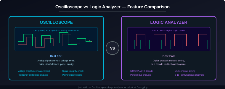
Table of Contents
- 1. The Fundamental Difference: Analog vs Digital
- 2. Oscilloscope Deep Dive: What It Measures
- 3. Logic Analyzer Deep Dive: What It Captures
- 4. Protocol Decoding: I2C, SPI, UART, CAN
- 5. Industrial Debugging Scenarios
- 6. Head-to-Head: Specifications That Matter
- 7. Combo Units: Oscilloscope + Analyzer in One
- 8. Buying Guide: Which Should You Buy First?
- 9. Frequently Asked Questions
1. The Fundamental Difference: Analog vs Digital
The core distinction between an oscilloscope and a logic analyzer comes down to what they measure. An oscilloscope captures the actual voltage waveform — the shape, amplitude, noise, and timing of analog signals. A logic analyzer captures digital logic states — whether a signal is HIGH or LOW at any given moment across many channels.
Think of it this way: if a signal is a spoken word, the oscilloscope records the exact sound wave (frequency, amplitude, distortion), while the logic analyzer transcribes the words (0s and 1s) without caring about the voice quality.
For industrial automation, this distinction matters because factory floor signals include both analog (4-20mA sensor loops, 0-10V control signals, PWM motor drives) and digital (I2C sensor buses, SPI chip selects, UART communication, relay states) signals. Knowing which tool to reach for depends on what problem you are trying to solve.
2. Oscilloscope Deep Dive: What It Measures
An oscilloscope samples voltage at extremely high rates — typically 1 GSa/s (gigasamples per second) for mid-range models. This allows it to capture signal details that a logic analyzer simply cannot see:
- Voltage amplitude: Measure the exact peak-to-peak voltage of a signal. Is your 5V rail actually 4.8V? Is the sensor output within spec? Only an oscilloscope tells you.
- Signal shape: Is the square wave truly square, or are the rise and fall times too slow? Is there ringing on the edges? Are there noise spikes? The oscilloscope shows the actual waveform shape.
- Frequency and period: Measure the exact frequency of a PWM signal, the period of a clock, or the oscillation frequency of a sensor output.
- Phase relationship: Compare the phase between two signals — critical for motor control timing and multi-phase power analysis.
- Noise and interference: Detect ground loops, electromagnetic interference, and signal crosstalk that would be invisible on a logic analyzer.
- Power quality: Measure voltage ripple on power supplies, analyze harmonic distortion, and check power factor on motor drives.
Industrial oscilloscopes add features for factory environments: isolated channels (preventing ground loops between measurement points), higher voltage ratings (up to 1000V CAT III), and ruggedized enclosures rated for dust and vibration.
3. Logic Analyzer Deep Dive: What It Captures
A logic analyzer excels at capturing digital signals across many channels simultaneously. Where an oscilloscope typically offers 2-4 channels, a logic analyzer provides 8, 16, or even 100+ channels at a fraction of the per-channel cost.
Key advantages of a logic analyzer for industrial debugging:
- Channel count: Capture 16 digital signals simultaneously — enough to monitor a full parallel bus, multiple I2C devices, or an entire PLC I/O card.
- Deep memory: Logic analyzers often have megasamples of capture memory, allowing you to record minutes of digital activity. An oscilloscope with the same sample rate might capture only milliseconds.
- Trigger flexibility: Set complex triggers like “capture when I2C address 0x50 appears AND the interrupt line goes LOW” — something impossible on most oscilloscopes.
- Threshold precision: Set the exact voltage threshold that defines HIGH vs LOW (1.8V, 3.3V, 5V, 12V, 24V). This eliminates ambiguity in mixed-voltage systems.
- Timing analysis: Measure the exact time between signal edges across multiple channels — critical for verifying setup and hold times on digital interfaces.
Logic analyzers come in two flavors: standalone benchtop units (Saleae Logic Pro 16, Analog Discovery Pro) and USB-connected modules (Saleae Logic 8, DSLogic). Both connect to PC software that provides waveform display, protocol decoding, and measurement tools.
4. Protocol Decoding: I2C, SPI, UART, CAN
Both modern oscilloscopes and logic analyzers offer protocol decoding — converting raw waveforms into human-readable bus transactions. However, the implementation differs significantly:
Oscilloscope Protocol Decode: Adds decoded bus transactions as an overlay on the analog waveform. You can see both the raw signal shape AND the decoded data simultaneously. Useful when you suspect signal integrity issues are causing protocol errors — you can see the actual voltage levels that produced each bit.
Logic Analyzer Protocol Decode: Provides a dedicated protocol viewer with auto-detection of clock and data lines. For I2C, it shows START condition, address byte, R/W bit, ACK/NACK, and data bytes in a clean list format. For SPI, it shows chip select, clock polarity, and data on MOSI/MISO lines. The decode is faster and more accurate because the logic analyzer is designed specifically for digital signal analysis.
Supported protocols on typical units:
- Both support: I2C, SPI, UART/USART, CAN, RS-232
- Oscilloscope only: LIN, FlexRay (on higher-end models)
- Logic analyzer only: Parallel bus, JTAG, custom protocols via scripting
- Both can decode: 1-Wire, SDIO, MIPI (with appropriate hardware)
For industrial Modbus RTU debugging (RS-485), the logic analyzer is the better choice because you need to capture both the A and B differential lines simultaneously, and the protocol decode handles the Modbus frame structure automatically.
5. Industrial Debugging Scenarios
Here are common factory floor problems and which tool to use for each:
Scenario 1: Sensor reading is erratic. Use the oscilloscope. Connect to the sensor output and look for noise, voltage dropouts, or signal distortion. A 4-20mA sensor with a corroded connector might show intermittent voltage spikes that a logic analyzer would miss entirely.
Scenario 2: I2C temperature sensor not responding. Use the logic analyzer. Capture SDA and SCL lines simultaneously. The decode shows whether the master is sending the correct address, whether the sensor ACKs, and whether data is valid. The oscilloscope would show the raw clock and data waveforms but would require manual bit-by-bit analysis.
Scenario 3: Motor VFD communication errors. Use the logic analyzer. Capture the RS-485 A/B lines over a complete Modbus transaction. The decode shows the master request, slave response, and any framing errors. If the error is timing-related, the logic analyzer shows the exact gap between bytes.
Scenario 4: Relay clicks but load does not activate. Use the oscilloscope. Measure the voltage across the relay contacts. If the relay clicks but the contact resistance is high (welded contacts), the oscilloscope shows the voltage drop. A logic analyzer cannot measure analog voltage — it would only show the relay coil drive signal as HIGH.
Scenario 5: SPI flash read errors on STM32. Use the logic analyzer. Capture CS, SCK, MOSI, MISO simultaneously. The decode shows the command byte, address, and data. Compare with the expected protocol sequence to identify whether the issue is in the command, the address, or the data phase.
6. Head-to-Head: Specifications That Matter
Here is a direct comparison of specifications for commonly used industrial debugging tools:
| Specification | Oscilloscope (Rigol DS1054Z) | Logic Analyzer (Saleae Logic Pro 16) |
|---|---|---|
| Channels | 4 analog | 16 digital |
| Sample Rate | 1 GSa/s | 500 MSa/s digital |
| Bandwidth | 50 MHz | N/A (digital threshold) |
| Memory Depth | 12 Mpts | 100 Mpts per channel |
| Protocol Decode | I2C, SPI, UART, CAN, RS232 | I2C, SPI, UART, CAN, JTAG, 1-Wire, MDIO |
| Voltage Range | -5V to +5V (with probe) | -2V to +5.5V (threshold selectable) |
| Price (approx.) | $400 | $500 |
For industrial work, the Saleae Logic Pro 16 offers isolated inputs — each channel is electrically isolated from the others and from the USB ground. This prevents ground loops when measuring signals on different power domains, a common problem in factory environments.
7. Combo Units: Oscilloscope + Analyzer in One
Several instruments combine oscilloscope and logic analyzer functionality in a single unit, eliminating the need to choose:
- Analog Discovery Pro (Digilent): 2-channel oscilloscope (100 MHz) + 16-channel logic analyzer in a USB-powered module. Software includes protocol decoding for I2C, SPI, UART, CAN. Price: $380.
- Hantek 6022BE: 2-channel oscilloscope (20 MHz) with 16-channel logic analyzer via bundled software. Budget option at $70, but limited sample rate (24 MSa/s) and no isolated inputs.
- Tektronix MDO3024: 4-channel oscilloscope (200 MHz) + 16-channel logic analyzer in a benchtop instrument. Professional grade with isolated inputs. Price: $2500+.
The Digilent Analog Discovery Pro is the best value for industrial engineers who need both tools but cannot justify buying separate instruments. Its isolation feature makes it safe for factory floor measurements, and the WaveForms software provides a unified interface for both oscilloscope and logic analyzer functions.
8. Buying Guide: Which Should You Buy First?
If you can only buy one tool, follow this decision tree:
Buy an oscilloscope first if:
- You work primarily with analog sensors (4-20mA, 0-10V, thermocouples)
- You need to measure voltage levels, not just logic states
- You debug power supplies, motor drives, or analog control loops
- You need to see signal noise, ringing, or distortion
Buy a logic analyzer first if:
- You work primarily with digital communication buses (I2C, SPI, UART, CAN)
- You need to capture many channels simultaneously (8+ signals)
- You need deep memory capture over long time periods
- You debug protocol errors rather than voltage issues
Buy both (or a combo unit) if:
- You work on mixed-signal embedded systems (STM32, Arduino, ESP32)
- You need to correlate analog events with digital protocol transactions
- Your debugging workflow requires both signal integrity and protocol analysis
For most industrial automation engineers, the oscilloscope is the more versatile first purchase. You can always use the Arduino’s Serial.print() to debug digital protocols, but there is no substitute for an oscilloscope when you need to see the actual voltage waveform.
Frequently Asked Questions
Can a logic analyzer measure 4-20mA sensor output?
No. A logic analyzer only detects whether a signal is above or below the threshold voltage — it cannot measure the actual voltage level. For a 4-20mA sensor, you need an oscilloscope to measure the voltage across the sense resistor (250 ohm gives 1-5V) and confirm the current is within the 4-20mA range.
Which is better for debugging RS-485 Modbus communication?
A logic analyzer with RS-485 differential probe is better for protocol-level debugging because it captures both A and B lines and decodes the Modbus frames automatically. However, an oscilloscope is better if you suspect physical layer issues like impedance mismatches, cable termination problems, or ground loop interference affecting signal quality.
Do I need isolated channels for industrial measurements?
Yes, if you are measuring signals on different power domains or connecting to equipment with separate ground references. Non-isolated instruments can create ground loops that corrupt measurements or damage the instrument. Isolated inputs (available on Saleae Logic Pro 16 and Tektronix MDO series) prevent this by breaking the ground connection between channels.
Can a logic analyzer trigger on specific I2C addresses?
Yes. Most logic analyzer software allows you to set trigger conditions on specific protocol values — including I2C addresses. For example, trigger on I2C address 0x50 with a write command, or on SPI chip select CS0 going LOW while MOSI shows command 0x03 (read). This is far more powerful than the simple edge triggering available on most oscilloscopes.
What sample rate do I need for industrial signals?
For most industrial digital signals (I2C at 400 kHz, SPI at 1-10 MHz, UART at 115200 baud), 100 MSa/s is more than sufficient. For high-speed signals like USB 2.0 (480 Mbps) or Ethernet (100BASE-TX), you need 1 GSa/s or higher. For analog signals, the Nyquist theorem requires at least 2x the signal frequency — so for a 50 MHz clock, you need at least 100 MSa/s.
Related Reading
- STM32 vs Arduino for Industrial Applications: Why Professionals Choose STM32
- I2C Communication Guide for Embedded Systems
- Industrial ADC Guide: Precision Analog-to-Digital Conversion
- Modbus TCP vs EtherNet/IP: Industrial Ethernet Protocols Compared
Sources
- Saleae Logic Analyzers — Product Page
- Digilent Analog Discovery Pro — Product Page
- Tektronix MDO3000 Series Oscilloscopes
- Rigol DS1000Z Series Oscilloscopes
- Electronic Design — Choosing Between Oscilloscope and Logic Analyzer
Disclosure: This post contains affiliate links. When you purchase through these links, we may earn a small commission at no additional cost to you. This supports our content creation and helps us provide free industrial automation guides.