Key Takeaway: The STM32 built-in bootloader lets you flash firmware over UART using just a USB-to-serial adapter and the free STM32CubeProgrammer tool — no ST-Link debug probe required. This guide walks through every boot mode, pin connection, and step-by-step DFU process so you can update field-deployed STM32 boards without opening the enclosure.
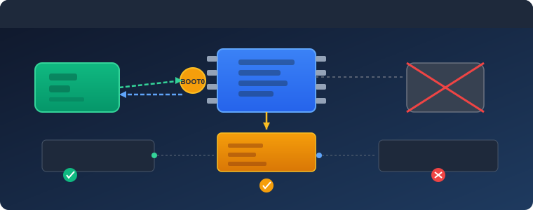
Table of Contents
- 1. What Is the STM32 System Bootloader?
- 2. STM32 Boot Modes: BOOT0 and BOOT1 Pin Configuration
- 3. UART Connection: Wiring the USB-to-Serial Adapter
- 4. Flashing Firmware with STM32CubeProgrammer
- 5. The STM32 UART Bootloader Protocol Explained
- 6. Step-by-Step DFU Firmware Update Workflow
- 7. Securing the Bootloader: Read/Write Protection
- 8. Troubleshooting Common Bootloader Issues
- 9. Frequently Asked Questions
- 10. Related Reading
- 11. Sources
1. What Is the STM32 System Bootloader?
Every STM32 microcontroller ships with a factory-programmed bootloader in system memory (often called the ROM bootloader). This bootloader is a small firmware routine burned into read-only memory during manufacturing that cannot be erased or overwritten by user code. When the chip powers up, it checks specific GPIO pins and, depending on their state, either runs the bootloader or jumps to your application code in flash.
The STM32 system bootloader supports several communication interfaces depending on the chip family: UART, USB DFU, SPI, I2C, and CAN. For field updates on deployed hardware, UART DFU is by far the most popular choice because it requires only a two-wire serial connection, works with any cheap USB-to-serial adapter, and does not need a functioning USB stack on the target board.
Understanding when the bootloader runs versus when your application runs is the foundation of reliable firmware update strategies. If you have ever had an STM32 board that refuses to respond to ST-Link or displays “no STM32 targets found” in the debugger, the chip is likely sitting in the bootloader waiting for serial commands — or the opposite, and it never entered bootloader mode at all.
2. STM32 Boot Modes: BOOT0 and BOOT1 Pin Configuration
The STM32 boot mode is determined by the logic levels on the BOOT0 and BOOT1 pins at the moment of reset. These are latched during the rising edge of NRST and held until the next reset cycle.
Standard boot mode selection for most STM32 families:
- BOOT0 = 0, BOOT1 = x: Boot from main flash memory — normal application execution.
- BOOT0 = 1, BOOT1 = 0: Boot from system memory — the factory ROM bootloader executes.
- BOOT0 = 1, BOOT1 = 1: Boot from embedded SRAM — useful for testing code without writing to flash.
Some STM32 families (like STM32F7, H7, and G4) use a more complex boot configuration with option bytes. Check the reference manual for your specific family.
Practical tip: If you are designing a new PCB, always route BOOT0 to a jumper or at minimum a solder bridge — you will thank yourself later when you need to do field updates.
3. UART Connection: Wiring the USB-to-Serial Adapter
The STM32 system bootloader uses USART1 by default. The connection is straightforward:
- TX from USB adapter → RX on STM32 (USART1_RX, PA10 on most F4/L4)
- RX on USB adapter → TX on STM32 (USART1_TX, PA9 on most F4/L4)
- GND between adapter and STM32
- 3.3V from adapter to STM32 VDD (optional, if board has no other power)
Common mistakes:
- Swapping TX and RX — the most frequent wiring error. Cross-connect: your TX goes to their RX and vice versa.
- Using a 5V adapter on a 3.3V-only STM32 — this can damage the chip.
- Forgetting common ground — without GND connected, communication fails silently.
- Missing the BOOT0 pin toggle — the chip runs your application instead of the bootloader.
4. Flashing Firmware with STM32CubeProgrammer
STM32CubeProgrammer is ST’s official tool for reading, writing, and verifying STM32 flash memory. Here is the UART DFU workflow:
Step 1: Connect the USB-to-serial adapter, set BOOT0 = 1, and press the reset button. The chip should now be in system memory bootloader mode.
Step 2: Open STM32CubeProgrammer, select “UART” from the connection type dropdown. Choose the correct COM port and set the baud rate (115200 recommended). Click “Connect.”
Step 3: Once connected, the programmer reads the chip ID and displays device information including flash size, device name, and bootloader version.
Step 4: Navigate to the “Erasing & Programming” section. Select your .bin or .hex file. Choose the start address (0x08000000 for main flash). Check “Verify programming.”
Step 5: Click “Start Programming.” The tool erases, writes, and verifies. On success, it displays “Download verified successfully.”
5. The STM32 UART Bootloader Protocol Explained
The STM32 UART bootloader uses a simple command-response protocol:
- 0x7F: Initial command byte to initiate communication. Bootloader responds with ACK (0x79) or NACK (0x1F).
- Get command (0x00): Returns bootloader version and supported commands.
- Get ID (0x02): Returns device ID for identification.
- Read Memory (0x11): Reads data from a specified address.
- Go (0x21): Jumps execution to a specified address.
- Erase (0x43/0x44): Erases flash memory pages.
- Write Memory (0x31): Writes data to flash.
Each command follows consistent framing with inverted-byte checksums for error detection.
6. Step-by-Step DFU Firmware Update Workflow
Preparation: Generate the .bin file, verify size, and transfer to the host computer.
Entering bootloader mode: Power off, set BOOT0 = 1, release NRST, connect serial adapter.
Flashing: Open STM32CubeProgrammer, select UART, connect, select .bin file, program.
Returning to normal: Power off, set BOOT0 = 0, power on — chip boots from flash.
For automated systems: External MCU controls NRST and BOOT0, sends 0x7F for sync, then erase and write commands.
7. Securing the Bootloader: Read/Write Protection
Read Protection (RDP):
- Level 0: No protection. Flash readable freely.
- Level 1: Flash unreadable via debug port or bootloader. Transitions back mass-erase flash.
- Level 2: Permanent. Debug interface permanently disabled.
Write Protection (WRP): Prevents specific flash sectors from being erased/programmed through the bootloader.
Recommendation: Keep RDP Level 0 during development. Set Level 1 for production. Reserve Level 2 for security-critical applications.
8. Troubleshooting Common Bootloader Issues
“No DFU detected”: Verify BOOT0 is actually high. Check with multimeter. Confirm TX/RX not swapped.
Erase/write fails: Check flash protection. Mass erase first if needed.
Application doesn’t run after programming: Verify BOOT0 is set back to 0. Check vector table placement.
Baud rate detection fails: Try lower baud rate (9600). Some adapters have inaccurate clocks.
“Wrong command received”: Ensure correct interface (UART not USB DFU). Check no other software is using the COM port.
Frequently Asked Questions
Can I update STM32 firmware without a physical BOOT0 pin toggle?
Yes. Application firmware can implement a software jump to the bootloader by setting the vector table offset and jumping to system memory at 0x1FFF0000. Many production firmware update systems use this approach.
What is the maximum firmware size the UART bootloader can flash?
The bootloader can program the entire available flash memory. Practical limit is your chip’s flash size (512 KB for STM32F407, 1 MB for STM32F429, 2 MB for STM32H743).
Does the STM32 UART bootloader support firmware encryption?
No. The factory bootloader does not encrypt firmware. For encrypted updates, implement a custom bootloader or use Secure Boot with your own encryption scheme.
Can I read back firmware from a chip?
Only if read protection is at Level 0. Level 1+ prevents reading via bootloader.
How do I know which bootloader version is on my STM32?
Use STM32CubeProgrammer’s “Get Version & Read Protection Status” command, or read address 0x1FFF0000.
Is UART bootloader faster than SWD?
Generally no. SWD at 4-8 MHz is much faster. UART at 115200 baud gives ~10-12 KB/s. Use SWD for development, UART for field updates.
Related Reading
Sources
- STMicroelectronics — AN2606: System Memory Boot Mode
- STMicroelectronics — STM32CubeProgrammer
- STMicroelectronics — RM0090: STM32F4 Reference Manual
Disclosure: This post contains affiliate links. If you purchase through these links, we may earn a small commission at no extra cost to you. We only recommend tools and equipment we use in our own workshops.