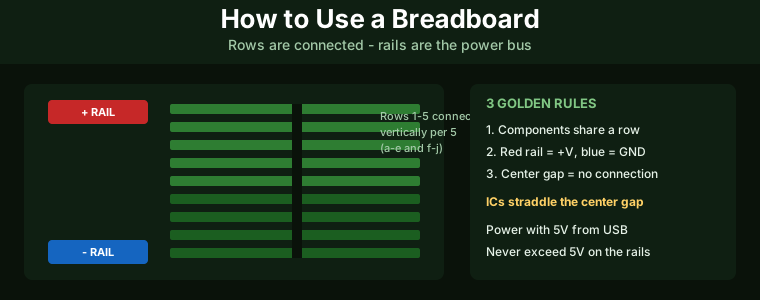
Key Takeaway: A breadboard lets you build and test electronic circuits without soldering. The rows of five holes are connected internally, and the long side rails are the power bus. Connect your components across rows, power the rails with 3.3V or 5V, and you can prototype almost any circuit in minutes.
Table of Contents
1. What Is a Breadboard and Why Use It
A breadboard is a reusable prototyping board with a grid of holes that are electrically connected in a fixed pattern underneath. You push component leads and jumper wires into the holes, and the internal metal clips make the connections. Because nothing is soldered, you can build a circuit, test it, change it, and take it apart in minutes — which makes breadboards perfect for learning electronics, testing ideas, and working with Arduino, ESP32, and STM32 development boards.
Whether you are following a tutorial, debugging a circuit, or designing something new, the breadboard is where the circuit lives before it earns a permanent home on a PCB.
2. Breadboard Anatomy Explained
Terminal strips (the middle area): The main grid of holes in the center. It is split into two halves by a horizontal channel down the middle. Each vertical column of five holes is connected internally, so a row of five holes acts like one node.
Power rails (the long side strips): The two long strips along each edge, marked with red (+) and blue (−) lines. Each full strip is a single continuous bus that carries power down the board. Split some boards’ rails in the middle, so you can use two different voltages on one board.
The center channel: The gap down the middle of the terminal strip. Its purpose is to let dual-inline (DIP) integrated circuits straddle it, with the pins on each side landing on different rows.
3. How Connections Actually Work
Inside the breadboard, each set of five holes in a column (labelled a-b-c-d-e and f-g-h-i-j) is connected by a spring clip. That means two components pushed into the same row of five are electrically connected to each other, but not to the adjacent rows. The two halves — rows a-e and rows f-j — are electrically separate from each other, which is why an IC placed across the center channel has each pin isolated on its own row.
The power rails work differently: every hole along the entire red strip is connected to every other hole on that strip, and the same for the blue strip. Jumper wires carry power from the rails into the terminal strips where your components live.
4. Your First Breadboard Circuit
Let us build the classic LED circuit. You will need a breadboard, one LED, one 220Ω resistor, and two jumper wires. This teaches you the core skills you will use in every breadboard project.
Step 1 — Connect power. Run a jumper from a 5V pin on your Arduino or ESP32 board to the red rail, and another from a GND pin to the blue rail.
Step 2 — Place the resistor. Push one resistor lead into a row on the terminal strip (say row 1), and the other lead into a different row (row 5). The resistor’s value is not critical here; 220Ω to 330Ω protects the LED.
Step 3 — Place the LED. Push the LED’s anode (longer lead) into the same row as the resistor’s second lead (row 5). Push the cathode (shorter lead) into another row (row 10).
Step 4 — Wire the rails. Use a jumper to connect the resistor’s first row (row 1) to the red rail, and another jumper to connect the LED’s cathode row (row 10) to the blue rail.
Power up the board and the LED should light. If it does not, check the LED polarity and swap the two leads.
5. The Rules of Good Breadboarding
- Never exceed 5V on the rails. Most breadboard circuits run at 3.3V or 5V. Higher voltages can melt the clips and damage components. Keep mains and bench supplies off the breadboard.
- Use one row per connection node. Every wire or lead that must connect together belongs in the same row of five holes.
- Colour-code your jumpers. Use red for power, black or blue for ground, and other colors for signals. It makes debugging dramatically easier.
- Cut jumper wires to length. Long spaghetti wires cause shorts and noise. Use solid-core hookup wire cut to the exact length, with the ends stripped 6mm.
- Keep the power rails tidy. Connect both ends of each rail to power when your circuit draws more current, because the internal clips have resistance.
6. Working with ICs and Modules
DIP integrated circuits sit across the center channel, with one row of pins on the top half and one on the bottom half. Each pin lands on its own row, giving you four extra connection points per pin. Push gently and evenly so no pin bends.
Development boards such as Arduino Uno, ESP32 DevKit, and STM32 Nucleo have male header pins. You can plug them directly into the breadboard, or use female-to-male jumper wires to connect them to the rows.
Sensors and modules with female headers (like many ESP32 sensor boards) connect with male-to-male jumper wires. Always power them from the rails and check their voltage rating before connecting anything to a 5V pin.
7. Common Problems and Fixes
The circuit does nothing. Check power first — is the board powered, and are the rails actually carrying voltage? Measure with a multimeter between the red and blue rails. Then check every component is pushed fully in, and that the leads are in the correct rows.
Wires keep falling out. Use solid-core wire, not stranded. Stranded wire compresses and loses contact. Breadboards also wear out; after heavy use, a worn column may stop making contact, and you can move that component to an unused row.
The LED is dim. You may have used too high a resistor, or the supply voltage is low. For a 5V supply, 220Ω gives about 12mA through a typical LED. For 3.3V, use 100-150Ω.
Nothing works after rearranging. Breadboards are mechanical devices. Remove everything and rebuild methodically, verifying each row’s continuity with a multimeter in the ohms range if needed.
8. Frequently Asked Questions
How do I use a breadboard for beginners?
Understand three facts: the five holes in each vertical column are connected, the long side rails are the power bus, and the center gap separates the two halves. Push components into the same row to connect them, use jumpers from the rails for power and ground, and you can build any beginner circuit.
Which rows are connected on a breadboard?
The five holes in each vertical column (a-e or f-j) are connected. The two halves of the board are not connected to each other across the center gap. The long red and blue rails are each fully connected along their length (some boards split in the middle).
Can I use a breadboard for permanent circuits?
Not recommended. Breadboard contacts are mechanical and can oxidize or loosen over time, and the clips have resistance that matters at higher currents. For a permanent build, transfer the circuit to a PCB or perfboard and solder it.
What is the maximum voltage for a breadboard?
Keep breadboard circuits at 5V or below. The clips are rated for low-current signal and logic circuits; using higher voltages risks melting the plastic and shorting the clips together. Bench power supplies should never feed a breadboard directly at more than 5V.
Why does my breadboard circuit not work?
Eighty percent of the time it is a power or ground problem. Verify the rails have voltage, confirm every component is in the correct row, check LED polarity, and make sure you are using solid-core jumper wire. A multimeter continuity check on each row usually finds the fault in minutes.
Related Reading
- How to Use a Digital Multimeter: Complete Guide
- How to Read Resistor Color Codes: Complete Guide
- Stepper Motor Control with DRV8825 and Arduino
- DIY ESP8266 Temperature and Humidity Monitor
Sources
- SparkFun – How to Use a Breadboard
- Science Buddies – How to Use a Breadboard
- All About Circuits – Building Resistor Circuits on Breadboards
- Build Electronic Circuits – How to Use a Breadboard
Disclosure: As an Amazon Associate, we earn from qualifying purchases. Some links on this page are affiliate links that help support our content at no extra cost to you.