Key Takeaway: Building your own ESP32 smart switch with relay control gives you complete control over home automation — it’s cost-effective, secure, and fully customizable with WiFi connectivity and manual override switches.
Table of Contents
1. Project Overview
An ESP32 smart switch is one of the most practical IoT projects you can build. It allows you to control electrical appliances — lights, fans, pumps, or any AC-powered device — from your smartphone via WiFi, while retaining physical push-button control as a backup. The total cost is under $25, significantly less than commercial smart switches, and you have full control over the firmware, features, and privacy.
The ESP32 microcontroller serves as the brain, handling WiFi connectivity, web server duties, and relay control logic. Its dual-core processor and built-in WiFi/Bluetooth make it ideal for this application. We’ll use an SPDT relay module for switching AC loads, and an HLK-PM01 AC-to-DC converter to power the ESP32 directly from mains voltage.
This project is suitable for anyone with basic soldering skills and a multimeter. We will provide complete code, wiring diagrams, and enclosure recommendations.
2. Components Required
Here is the complete bill of materials for a 2-channel ESP32 smart switch:
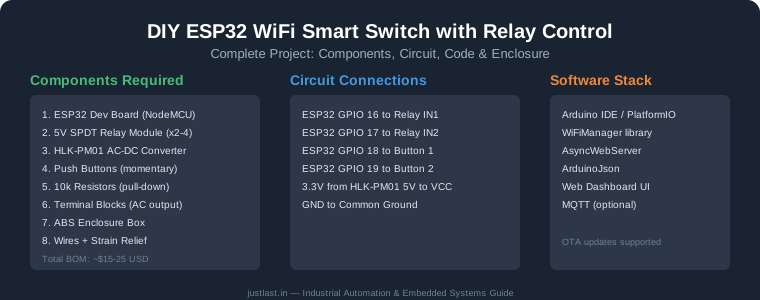
- ESP32 NodeMCU development board (any variant with at least 4 MB flash)
- 2-channel 5V SPDT relay module (rated for 10A at 250V AC)
- HLK-PM01 AC-to-DC converter module (240V AC to 5V DC, 600 mA)
- 2x momentary push buttons (SPST, normally open)
- 2x 10k ohm resistors (pull-down for buttons)
- 2-way screw terminal blocks for AC input and output
- ABS enclosure box (minimum 120x80x50 mm)
- Heavy-duty wires (0.75-1.5 mm² for AC wiring)
- Strain relief glands for cable entry points
- Veroboard or prototype PCB for assembly
Estimated cost: $15-25 from AliExpress, Amazon, or local electronics distributors.
3. Circuit Diagram and Wiring
The ESP32 smart switch circuit is straightforward. Connect the components as follows:
Power Supply: Connect the HLK-PM01 to mains AC (L and N inputs). Its 5V output goes to the ESP32’s 5V pin and relay module VCC. Common ground connects all GND terminals.
Relay Control: Connect ESP32 GPIO 16 to Relay IN1 (channel 1) and GPIO 17 to Relay IN2 (channel 2). The relay module’s JD-VCC jumper should remain connected for standard operation.
Push Buttons: Connect one button between GPIO 18 and GND (with 10k pull-up resistor to 3.3V), and the second button between GPIO 19 and GND (with pull-up resistor). These provide manual override control even when the web interface is unavailable.
Load Wiring: Connect the AC load (light, fan, etc.) to the relay’s COM (common) and NO (normally open) terminals. When the relay is activated, the circuit closes and the appliance turns on.
4. ESP32 Programming Code
The firmware for the ESP32 smart switch uses the following key libraries: WiFiManager for easy network configuration without hardcoding credentials, AsyncWebServer for responsive web control, and ArduinoJson for handling API requests.
The main program structure includes:
- WiFiManager portal (auto-launches on first boot for WiFi setup)
- AsyncWebServer with REST API endpoints (/on, /off, /toggle, /status)
- Button interrupt handlers for physical switch control
- State persistence using Preferences library (EEPROM-like storage)
- OTA update support for wireless firmware upgrades
The relay states are stored in non-volatile memory so the smart switch remembers its state after a power outage. Each relay channel has its own timer and status tracking for future scheduling features.
5. Web Dashboard Setup
The web dashboard served by the ESP32 smart switch includes:
- Status indicators for each relay channel (ON/OFF with color coding)
- Toggle buttons with real-time feedback via AJAX
- WiFi signal strength indicator
- System information (uptime, IP address, firmware version)
The dashboard is built using HTML, CSS, and JavaScript served directly from the ESP32’s flash memory. The design is responsive and works on both desktop browsers and mobile devices. For advanced users, the code can be extended with MQTT integration for use with Home Assistant, OpenHAB, or other home automation platforms.
6. Enclosure Assembly
Proper enclosure assembly is critical for the ESP32 smart switch’s safety and longevity. Use an ABS or polycarbonate enclosure rated for electrical use. Follow these steps:
- Drill holes for strain relief glands (one for mains input, two for load outputs)
- Mount the HLK-PM01 module with standoffs to prevent contact with conductive surfaces
- Secure the relay module using M3 screws and nuts
- Place the ESP32 on the opposite side from AC wiring to minimize interference
- Use heat shrink tubing on all AC connections
- Label all terminals clearly inside the enclosure
- Add a power indicator LED visible through the enclosure
7. Safety Considerations
Working with mains AC voltage (110-240V) carries serious risks. Follow these safety rules for your ESP32 smart switch project:
- Always disconnect mains power before opening the enclosure
- Use appropriately rated relays (at least 10A for general-purpose use)
- Include a fuse on the AC input (1-2A slow-blow recommended)
- Ensure at least 5 mm clearance between low-voltage (ESP32) and high-voltage areas
- Test with a multimeter before connecting loads
- Consider having an electrician verify the final installation
- NEVER exceed the relay’s rated current
Frequently Asked Questions
Can I control the ESP32 smart switch from anywhere?
Yes, with port forwarding on your router or a secure tunneling service. For remote access without exposing your network, consider setting up a VPN (WireGuard or OpenVPN) or using a cloud MQTT broker.
How many appliances can one ESP32 control?
A typical ESP32 can control 4-8 relay channels using available GPIO pins. For more channels, use an I2C GPIO expander (MCP23017) which adds 16 more I/O pins while using only two ESP32 pins.
Is the ESP32 smart switch energy-efficient?
The ESP32 in deep sleep mode consumes approximately 10 µA. However, for a smart switch that needs instant WiFi response, the active power consumption is around 75-200 mA at 5V (about 0.4-1W). This is comparable to commercial smart switches with similar features.
Can I use this with voice assistants?
Yes, by adding MQTT support and integrating with Home Assistant, the ESP32 smart switch can be controlled via Amazon Alexa, Google Home, or Apple HomeKit.
Related Reading
Sources
- Espressif ESP32 Technical Reference Manual
- WiFiManager Library for ESP32
- Adafruit – HLK-PM01 AC-DC Converter Guide
- DigiKey – Smart Switch Design Considerations
Disclosure: This post contains affiliate links. We may earn a commission on qualifying purchases at no additional cost to you.