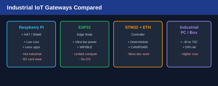
Key Takeaway: The ESP32 makes an ideal low-cost industrial IoT gateway for bridging Modbus RTU/TCP field devices to MQTT cloud platforms. This guide walks through hardware setup, firmware architecture, and the core code needed to build a reliable Modbus-to-MQTT bridge for factory monitoring.
Table of Contents

1. System Overview
In factory automation environments, sensors and actuators commonly communicate over Modbus RTU (RS-485) or Modbus TCP (Ethernet). However, these field devices are not directly internet-accessible, and running long RS-485 cables to a central SCADA system is expensive and inflexible. The solution is a local gateway that reads Modbus registers and publishes the data to an MQTT broker over WiFi or Ethernet.
The ESP32 is uniquely suited for this role because it offers:
- Dual-core processor with plenty of headroom for protocol translation
- Built-in WiFi and Bluetooth (optional BLE gateway)
- Two UART interfaces — one for debugging, one for RS-485 Modbus
- FreeRTOS support for real-time task scheduling
- Low power consumption (~80mA active, suitable for 24/7 operation)
- Cost: under $5 per unit in modest quantities
2. Hardware Requirements
Core components for one gateway node:
- ESP32 Dev Board — ESP32-WROOM-32 or ESP32-S3 (recommended for more GPIO)
- RS-485 Transceiver — MAX485 or MAX3485 TTL-to-RS485 module (under $2)
- 5V Power Supply — 1A minimum for stable operation
- 24V-5V DC-DC Converter — if powering from industrial 24V supply
- Termination Resistors — 120 ohm at each end of the RS-485 bus (for cables over 100m)
Optional: Industrial DIN-rail enclosure, surge protection (TVS diodes on RS-485 lines), and an OLED display for local diagnostics.
3. Wiring the RS-485 Interface
The MAX485 module connects to the ESP32 as follows:
- VCC → ESP32 5V pin (or 3.3V for MAX3485)
- GND → ESP32 GND (critical — common ground with all Modbus devices)
- RO (Receiver Output) → ESP32 RX2 (GPIO16)
- DI (Driver Input) → ESP32 TX2 (GPIO17)
- RE & DE (Receiver/Driver Enable) → ESP32 GPIO4 (tied together, controlled by library)
- A → RS-485 A/+ line (differential pair)
- B → RS-485 B/- line (differential pair)
For Modbus RTU, set the ESP32 UART to 9600 baud (default for most industrial devices), 8 data bits, no parity, 1 stop bit (8N1).
4. ESP32 Firmware Architecture
The firmware uses a FreeRTOS task structure with three main tasks:
Task 1: Modbus Polling (1000ms interval)
This task runs on Core 1 and handles all Modbus communication. It sends read requests to each configured Modbus slave device, parses the response, and updates a shared data structure protected by a mutex.
Task 2: MQTT Publish (1000-5000ms interval)
This task runs on Core 0 and reads the shared data, formats it as JSON, and publishes to the MQTT broker. The WiFi connection is maintained in this task using the PubSubClient or AsyncMQTTClient library.
Task 3: Watchdog & Diagnostics (60000ms interval)
Reports uptime, WiFi signal strength (RSSI), Modbus error count, and free heap memory to a separate MQTT diagnostics topic.
5. Core Modbus-to-MQTT Code
The essential libraries needed for this project:
- ModbusMaster — handles Modbus RTU protocol over RS-485
- PubSubClient or AsyncMQTTClient — MQTT client for ESP32
- ArduinoJson — JSON formatting for MQTT payloads
#include <ModbusMaster.h>
#include <PubSubClient.h>
#include <WiFi.h>
#include <ArduinoJson.h>

// Configuration
#define MODBUS_BAUD 9600
#define MODBUS_SLAVE_ID 1
#define MODBUS_DE_RE_PIN 4
#define MQTT_TOPIC "factory/sensor1"

ModbusMaster modbus;
WiFiClient wifiClient;
PubSubClient mqtt(wifiClient);

void setup() {
  Serial.begin(115200);

  WiFi.begin("SSID", "PASSWORD");
  while (WiFi.status() != WL_CONNECTED) delay(500);

  mqtt.setServer("mqtt-broker.local", 1883);

  Serial2.begin(MODBUS_BAUD, SERIAL_8N1, 16, 17);
  modbus.begin(MODBUS_SLAVE_ID, Serial2);
  pinMode(MODBUS_DE_RE_PIN, OUTPUT);
  digitalWrite(MODBUS_DE_RE_PIN, LOW);
}

void loop() {
  static uint8_t result;
  uint16_t registers[10];

  // Read 10 holding registers from slave
  result = modbus.readHoldingRegisters(0, 10);

  if (result == modbus.ku8MBSuccess) {
    for (int j = 0; j < 10; j++) {
      registers[j] = modbus.getResponseBuffer(j);
    }

    // Format as JSON
    StaticJsonDocument<256> doc;
    doc["temperature"] = registers[0] / 10.0;
    doc["pressure"] = registers[1];
    doc["humidity"] = registers[2] / 10.0;
    char json[256];
    serializeJson(doc, json);

    // Publish to MQTT
    if (mqtt.connected()) {
      mqtt.publish(MQTT_TOPIC, json);
    }
  }

  delay(1000);
}
6. Deployment & Testing
Step 1: Lab test — Connect the ESP32 to a single Modbus sensor on your bench. Verify register values with a Modbus scanner tool (like QModMaster or Simply Modbus).
Step 2: MQTT test — Use an MQTT client (Mosquitto, MQTT Explorer) to subscribe to the topic and verify JSON payloads arrive at the expected interval.
Step 3: Field deployment — Mount the ESP32 in a DIN-rail enclosure near the sensor cluster. Connect to the facility’s 24V supply via the DC-DC converter. Verify WiFi signal strength at the installation location — below -70dBm RSSI indicates a weak connection that may cause intermittent disconnections.
Step 4: Scale — Deploy one ESP32 gateway per zone (typically 5-15 meters of RS-485 cabling). Use unique MQTT topics per zone: factory/zone1/sensors, factory/zone2/sensors, etc.
Frequently Asked Questions
Can the ESP32 handle multiple Modbus slaves on one RS-485 bus?
Yes. Modbus RTU supports up to 247 devices on a single RS-485 bus (limited by electrical drive capability). The ESP32 polls each slave sequentially by their unique ID. Set a polling interval of 100-200ms per device for a 10-device bus, you’ll get a 1-2 second update cycle.
What MQTT broker should I use?
For local deployments, Mosquitto on a Raspberry Pi or industrial gateway is free and reliable. For cloud connectivity, use AWS IoT Core, Azure IoT Hub, or a dedicated MQTT cloud service. The ESP32 connects to the local broker; the local broker can bridge to the cloud if needed.
How do I handle WiFi disconnections?
Implement a reconnection loop with exponential backoff. The ESP32 WiFi library includes auto-reconnect — enable it with WiFi.setAutoReconnect(true). Buffer Modbus readings locally (in an array or SPIFFS file) during disconnection and publish them when connectivity returns.
Is the ESP32 reliable for 24/7 industrial use?
With proper power supply filtering, a watchdog timer (enable the ESP32 hardware watchdog), and a robust enclosure, the ESP32 is suitable for light industrial use. For critical applications requiring certified industrial reliability, consider the ESP32-S3 or a dedicated industrial IoT gateway — but for monitoring and non-safety-critical control, the ESP32 performs well.
Related Reading
Sources
Disclosure: This post contains affiliate links. As an Amazon Associate we earn from qualifying purchases.