Key Takeaway: Choosing between conventional and climb milling directly affects your surface finish quality, tool life, and machining accuracy — and the right choice depends on your machine rigidity, not just personal preference.
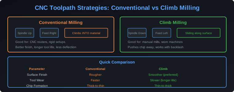
Table of Contents
1. Conventional Milling Explained
Conventional milling, also known as up milling, is a toolpath strategy where the cutting tool rotates against the direction of the feed movement. The chip starts at zero thickness at the beginning of each tooth’s engagement and grows thicker as the tooth exits the material. This thick-to-thin chip formation is the defining characteristic of conventional milling and has significant implications for tool wear, surface finish, and cutting forces.
In conventional milling, the cutting forces push the workpiece away from the cutter and tend to lift the spindle upward. On a manual mill with backlash in the lead screws, this is actually beneficial — the constant upward force takes up the backlash and prevents the table from being pulled into the cutter unpredictably. This is why conventional milling was the dominant strategy for decades on manual machines.
The disadvantage of conventional milling is the rubbing that occurs at the start of each chip. Because the chip starts at zero thickness, the cutting edge initially rubs across the material surface before it begins to actually cut. This rubbing generates heat, accelerates tool wear, and can cause work hardening on materials like stainless steel and titanium. The surface finish from conventional milling tends to be rougher because of this rubbing action and the higher cutting forces involved.
For CNC machining with ball screw drives and no backlash, conventional milling is generally the inferior choice. However, it still has valid applications: when machining hard materials where you want the cutting forces to push the workpiece into the fixture rather than pulling it away, and when the workpiece setup lacks rigidity and you need the upward cutting force component to minimize workpiece deflection.
2. Climb Milling Explained
Climb milling, also called down milling, is a toolpath strategy where the cutting tool rotates in the same direction as the feed movement. The chip starts at maximum thickness when the tooth first engages the material and thins to zero as the tooth exits. This thin-to-thick chip formation is the opposite of conventional milling and produces fundamentally different cutting behavior.
In climb milling, the cutting forces push the workpiece into the table and pull the cutter downward toward the workpiece. This creates a more rigid cutting system where the forces are absorbed by the machine structure rather than fighting against it. On a CNC machine with ball screw drives and minimal backlash, climb milling is almost always the preferred strategy.
The benefits of climb milling are significant. Tool life typically increases by 30-50% compared to conventional milling because the cutting edge enters the material at maximum chip thickness, eliminating the rubbing phase that generates heat and accelerates wear. Surface finish quality improves dramatically because the clean shearing action produces a smoother surface with less built-up edge on the cutting tool. Cutting forces are lower and more predictable, which reduces the chance of tool deflection and improves dimensional accuracy.
The main limitation of climb milling is that it requires a rigid machine with minimal backlash. On a machine with loose lead screws or worn gibs, the cutting forces can pull the table into the cutter, causing chatter, poor finish, and in extreme cases, tool breakage. If your CNC machine has backlash greater than 0.002 inches (0.05 mm), you should address the backlash issue before switching to climb milling, or stick with conventional milling for roughing operations.
3. Head-to-Head Comparison
Understanding the specific differences between these two strategies helps you make informed decisions for every cutting operation.
Surface finish: Climb milling produces a significantly better surface finish. The thin-to-thick chip formation creates a clean shearing action that leaves a smooth surface. Conventional milling’s rubbing action creates a rougher surface with visible feed marks. For finishing passes where surface quality matters, climb milling is almost always the right choice.
Tool life: Climb milling extends tool life by 30-50% in most materials. The elimination of the rubbing phase means less heat generation at the cutting edge, which preserves the tool’s sharp edge longer. In abrasive materials like cast iron or fiberglass composites, the difference in tool life between the two strategies can be even more dramatic.
Cutting forces: Conventional milling generates higher and more variable cutting forces, particularly at the entry point. Climb milling produces more consistent forces throughout the cut. This consistency is important for maintaining dimensional accuracy, especially on thin-walled parts or when machining near the limit of your machine’s rigidity.
Chip evacuation: Climb milling tends to throw chips forward, away from the cut zone, which is better for chip evacuation. Conventional milling pulls chips back into the cut zone, which can cause chip re-cutting and poor surface finish in materials that produce long, stringy chips like aluminum.
Workholding forces: Conventional milling pushes the workpiece away from the cutter and upward, while climb milling pushes the workpiece into the fixture and downward. Choose conventional milling when your workholding is marginal and you want the forces working in your favor. Choose climb milling when your workholding is solid and you want the machine structure absorbing the cutting forces.
4. When to Use Each Strategy
Use climb milling when:
- You have a rigid CNC machine with ball screw drives and less than 0.002″ backlash
- You want the best possible surface finish
- You are machining aluminum, plastics, or soft materials where tool life matters
- You are doing finishing passes where dimensional accuracy is critical
- You want to maximize tool life and reduce tooling costs
Use conventional milling when:
- Your machine has significant backlash in the lead screws
- You are roughing hard materials (tool steel, titanium) and need cutting forces to push the workpiece into the fixture
- The workpiece setup is not rigid and you need to minimize workpiece deflection
- You are machining a thin-walled part that could be pulled away from the fixture by climb milling forces
- You are using a large-diameter cutter where the cutting forces are high and you need maximum workpiece stability
5. Other CNC Toolpath Strategies You Should Know
Beyond the conventional vs climb decision, CNC programmers have access to several toolpath strategies that optimize for different goals.
Contour (profile) toolpaths follow the part profile at a constant depth, stepping down incrementally for each pass. This is the most common roughing strategy and works well with both climb and conventional milling. The step-down depth should be 50-75% of the cutter diameter for optimal tool life.
Pocket clearing toolpaths remove material from enclosed areas. Modern CAM software offers adaptive clearing or trochoidal milling strategies that maintain a constant tool engagement angle, reducing cutting forces and heat buildup. These strategies are particularly effective in hard materials and deep pockets.
Waterline (Z-level) toolpaths cut at constant Z heights, following the part contour at each level. They are excellent for finishing steep walls and are commonly used in mold and die making where surface finish on vertical walls is critical.
Spiral and helical toolpaths ramp into the material gradually rather than plunging straight down. This eliminates the need for a plunge cut and allows you to use end mills that are not designed for plunging, such as ball nose cutters or roughing end mills with chip-breaker geometries.
6. Optimizing Toolpaths in CAM Software
Modern CAM software like Fusion 360, SolidWorks CAM, and Mastercam gives you fine control over toolpath parameters that directly impact machining efficiency and part quality.
Stepover and stepdown: For roughing, use a stepover of 50-70% of the cutter diameter and a stepdown of 50-100% of the flute length. For finishing, reduce the stepover to 5-10% of the cutter diameter to achieve a smooth surface. The scallop height formula (h = s² / 8R, where s is stepover and R is cutter radius) helps you calculate the exact stepover needed for a target surface finish.
Lead-in and lead-out moves: The way the cutter enters and exits the material has a significant impact on surface finish. Use arc lead-ins at 45-90 degrees to the cut direction, with a radius equal to or greater than the cutter diameter. This prevents dwell marks and ensures the cutter is at full engagement before it contacts the finish surface.
Rest machining: After a roughing pass with a large cutter, use rest machining to clean up material left in corners and tight areas with a smaller cutter. This eliminates hand finishing and ensures consistent surface finish across the entire part. Most modern CAM packages detect remaining stock automatically and generate optimized rest-machining toolpaths.
Frequently Asked Questions
Why do most CNC programmers prefer climb milling?
CNC machines are designed for climb milling. The ball screw drives eliminate backlash, the rigid construction absorbs cutting forces, and the digital control maintains precise feed rates. Climb milling takes advantage of these characteristics to produce better surface finish, longer tool life, and more accurate parts. The preference is not arbitrary — it is a direct consequence of how modern CNC machines are built.
Can I mix conventional and climb milling in the same part?
Absolutely. Many experienced programmers use conventional milling for roughing in hard materials where the upward cutting forces help keep the workpiece in the fixture, then switch to climb milling for finishing passes where surface quality matters. The key is understanding why each strategy is appropriate for its specific operation rather than applying a one-size-fits-all approach.
Does climb milling produce thinner chips?
Yes, climb milling produces thicker chips at entry and thinner chips at exit, while conventional milling produces the opposite. The thicker initial chip in climb milling means the cutting edge engages the material immediately without rubbing, which generates less heat and produces a cleaner cut. The chip thickness variation also affects the optimal feed rate — you may need to adjust feeds to maintain consistent chip load.
How does toolpath strategy affect CNC machine wear?
Climb milling produces lower and more consistent cutting forces, which reduces wear on spindle bearings, ball screws, and linear guides. Conventional milling’s higher and more variable forces accelerate wear on all machine components, particularly during heavy roughing cuts. Over thousands of hours of operation, using climb milling where appropriate can meaningfully extend your CNC machine’s service life.
Related Reading
- Complete Guide to CNC Milling Operations: Face, Slot, Contour and Pocket Milling
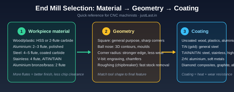
- CNC End Mills and Tooling: Complete Guide to Flute Count, Coatings and Feeds
- SolidWorks CAM vs Mastercam: Professional CAM Software for CNC Programming
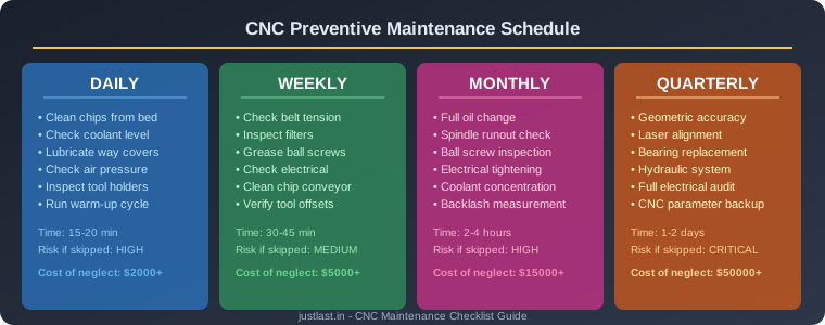
- CNC Preventive Maintenance Schedule: Complete Checklist for Lathes and Mills
Sources
- Harvey Performance — Climb Milling vs Conventional Milling
- CNCCookbook — Climb vs Conventional Milling Guide
- Machinist Blog — When to Use Each Milling Strategy
- Practical Machinist — Climb vs Conventional Discussion
- Autodesk Fusion 360 — CAM Toolpath Strategies
Disclosure: This post contains affiliate links. If you purchase through these links, we may earn a commission at no additional cost to you.