Key Takeaway: Industrial ADC techniques using STM32 microcontrollers enable precision analog-to-digital conversion for factory sensors, process control, and motion systems — with resolution up to 24-bit and sampling rates exceeding 1 MSPS when using the right ADC architecture and signal conditioning.
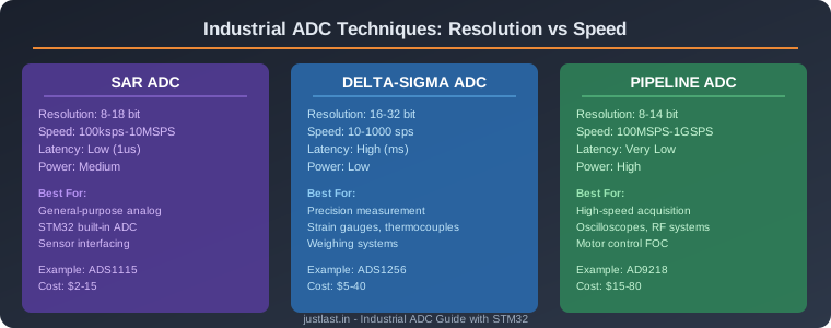
Table of Contents
1. Why ADC Matters in Industrial Systems
Every industrial sensor — temperature, pressure, flow, force, position — outputs an analog signal. A thermocouple produces millivolts, a strain gauge outputs microvolts, and a pressure transmitter generates 4–20mA. Before a microcontroller like the STM32 can process this data, it must be converted from analog to digital. The quality of this conversion directly determines the accuracy of your measurement system.
In industrial automation, poor ADC performance leads to:
- Incorrect sensor readings: Temperature drift, pressure fluctuations, and force measurements become unreliable
- Noise susceptibility: Factory environments are electrically noisy — motors, VFDs, and switching power supplies create interference
- Reduced control loop performance: ADC noise limits the minimum detectable change, degrading PID control quality
- Calibration difficulties: Poor linearity and offset errors require complex calibration procedures
Understanding ADC architectures and their trade-offs is essential for designing reliable industrial measurement systems. The choice between SAR, Delta-Sigma, and pipeline ADCs depends on your specific requirements for resolution, speed, and noise rejection.
2. ADC Types: SAR, Delta-Sigma, and Pipeline
SAR (Successive Approximation Register) ADC
The SAR ADC is the workhorse of industrial measurement. It works by comparing the input voltage against a reference voltage using a binary search algorithm. Each bit of the result is determined by testing whether the input is above or below the current midpoint voltage.
SAR ADC characteristics:
- Resolution: 8–18 bits (12-bit is most common)
- Speed: 100 kSPS to 10 MSPS
- Latency: Very low (typically 1 conversion cycle)
- Power consumption: Medium (1–50 mW)
- Best for: General-purpose analog measurement, fast multiplexed channels
The STM32 family includes built-in SAR ADCs with 12-bit resolution (4096 levels). For a 0–3.3V input range, this gives 0.8 mV per step — adequate for many industrial applications but insufficient for precision measurement of low-level signals.
Delta-Sigma ADC
The Delta-Sigma ADC trades speed for extreme resolution. It oversamples the input at high frequency, then uses digital filtering and decimation to produce very high-resolution output. This architecture excels at measuring slowly-changing signals with extreme precision.
Delta-Sigma ADC characteristics:
- Resolution: 16–32 bits (24-bit is common for industrial use)
- Speed: 10–1000 samples per second
- Latency: High (multiple clock cycles for digital filter settling)
- Power consumption: Low (1–5 mW)
- Best for: Strain gauges, thermocouples, precision voltage measurement
Popular industrial Delta-Sigma ADCs include the ADS1256 (24-bit, 30 kSPS) and ADS1248 (24-bit, designed for thermocouple measurement). These are commonly used in PLC analog input modules and industrial weighing systems.
Pipeline ADC
The pipeline ADC processes the input through multiple stages in a pipeline, with each stage resolving one or more bits. This architecture achieves high speed by processing multiple conversions simultaneously in different pipeline stages.
Pipeline ADC characteristics:
- Resolution: 8–14 bits
- Speed: 100 MSPS to 1 GSPS
- Latency: Very low (typically 3–5 clock cycles)
- Power consumption: High (50–500 mW)
- Best for: High-speed data acquisition, oscilloscopes, RF systems
Pipeline ADCs are rarely used in general industrial measurement but are essential for high-speed applications like motor control current sensing (field-oriented control) and vibration analysis.
3. STM32 Built-in ADC: Getting the Most from 12 Bits
The STM32 family includes 12-bit SAR ADCs that are surprisingly capable for industrial applications when properly configured. Here are the key techniques to maximize performance:
Technique 1: Oversampling and decimation
STM32 ADCs support hardware oversampling. By averaging multiple samples, you effectively increase resolution. Averaging 16 samples gains 2 extra bits (14-bit effective resolution). Averaging 256 samples gains 4 bits (16-bit effective). The STM32H7 series includes a dedicated hardware oversampling unit that performs this without CPU intervention.
Technique 2: DMA-based continuous conversion
Using DMA (Direct Memory Access) to transfer ADC results to memory eliminates CPU overhead and ensures no conversions are missed. Configure the ADC in continuous scan mode with DMA circular buffer for uninterrupted multi-channel acquisition.
Technique 3: Proper reference voltage
The STM32 internal reference voltage (VREFINT) varies between devices. For precision measurement, use an external precision voltage reference (e.g., REF3030 for 3.0V) connected to the VREF+ pin. This provides a stable, temperature-compensated reference.
Technique 4: Sampling time optimization
The STM32 ADC sampling time is configurable (1.5 to 810.5 clock cycles). For high-impedance sources, use longer sampling times to allow the internal sample-and-hold capacitor to charge fully. For low-impedance sources, shorter sampling times maximize throughput.
4. External ADC Chips for Higher Resolution
When the STM32’s 12-bit ADC is insufficient, external ADC chips provide the needed resolution and accuracy. Here are the most common choices for industrial applications:
| Chip | Resolution | Speed | Interface | Best For |
|---|---|---|---|---|
| ADS1115 | 16-bit | 860 SPS | I2C | General-purpose, Arduino/STM32 |
| ADS1256 | 24-bit | 30 kSPS | SPI | Precision measurement, strain gauges |
| ADS1248 | 24-bit | 2 kSPS | SPI | Thermocouple, RTD measurement |
| AD7124-8 | 24-bit | 15 kSPS | SPI | Industrial process control |
| LTC2500-32 | 32-bit | 1 MSPS | Parallel | Ultra-precision, metrology |
I2C vs SPI for ADCs: Use I2C for low-speed, low-pin-count applications (ADS1115). Use SPI for high-speed, multi-channel applications (ADS1256, AD7124). SPI provides higher throughput and lower latency, critical for real-time industrial control.
5. Signal Conditioning for Industrial Sensors
An ADC is only as good as the signal it receives. Industrial sensors produce signals that require conditioning before conversion:
Thermocouple signal conditioning:
- Signal level: 10–50 microvolts per degree C
- Required amplification: 100–500x
- Cold junction compensation (CJC) required
- Recommended: ADS1248 with built-in CJC and programmable gain amplifier
Strain gauge / load cell signal conditioning:
- Signal level: 1–3 mV full scale (typically 2 mV/V excitation)
- Required amplification: 500–1000x
- Wheatstone bridge excitation required
- Recommended: ADS1256 with instrumentation amplifier front-end
4–20mA current loop signal conditioning:
- Signal level: 4–20mA over 250 ohm resistor = 1–5V
- No amplification needed — direct ADC input
- Isolation recommended for high-noise environments
- Recommended: STM32 built-in 12-bit ADC with external precision reference
Noise reduction techniques for industrial environments:
- Use differential signaling where possible (reduces common-mode noise)
- Place ADC as close to the sensor as possible (minimize analog trace length)
- Add 100nF ceramic capacitors at every ADC power pin
- Use separate analog and digital ground planes with single-point connection
- Add RC low-pass filters at ADC inputs (cutoff at 10x the signal bandwidth)
Frequently Asked Questions
Can I use the STM32 ADC for industrial temperature measurement?
Yes, with proper signal conditioning. The STM32’s 12-bit ADC provides 0.8 mV resolution per step. For thermocouple measurement, add an external instrumentation amplifier (gain 100–200x) and cold junction compensation sensor. For RTD measurement (PT100), use a constant current source and bridge circuit. For most industrial applications, an external 24-bit ADC (ADS1248) provides better accuracy with less design effort.
What is the difference between ADC resolution and accuracy?
Resolution is the number of discrete levels the ADC can output (12 bits = 4096 levels). Accuracy is how close the digital output matches the true analog input. A 12-bit ADC with ±2 LSB accuracy has an error of ±0.05% of full scale. Resolution without accuracy is meaningless — always check the INL (Integral Non-Linearity) and DNL (Differential Non-Linearity) specifications.
How do I reduce ADC noise in a factory environment?
Key strategies: (1) Use differential ADC inputs to reject common-mode noise, (2) Add hardware averaging/oversampling in the STM32, (3) Use shielded cables for analog signals, (4) Place ADC circuitry away from motor drives and VFDs, (5) Use ferrite beads on power lines to the ADC, (6) Implement software digital filters (moving average, median filter) in firmware.
Which ADC should I use for a PLC analog input module?
For a 4–20mA PLC input module: STM32 built-in 12-bit ADC with 250-ohm precision resistor is sufficient. For thermocouple input module: ADS1248 (24-bit with built-in CJC). For strain gauge input: ADS1256 (24-bit with PGA). For multi-channel voltage input: ADS1115 (16-bit, 4 channels, I2C — simple and cost-effective).
Related Reading
- STM32 vs Arduino: Which Microcontroller for Motion Control?
- STM32 PWM Motor Control: Timer Configuration and Code
- I2C Communication Guide: STM32 and Arduino Interfacing
- MQTT for Industrial IoT: Complete Implementation Guide
Sources
- STMicroelectronics — STM32 ADC Modes and Usage (AN4443)
- Texas Instruments — Understanding Delta-Sigma ADCs
- Analog Devices — ADC Fundamentals
- Texas Instruments — Data Conversion Handbook for Industrial Applications
Disclosure: This post contains affiliate links. If you purchase through these links, we may earn a commission at no additional cost to you. This helps support our content creation.