I2C Communication Complete Guide: ESP32 vs STM32 Wiring, Addressing and Debugging
Key Takeaway
I2C communication is the most common sensor interface in embedded systems, but wiring errors, address conflicts, and voltage mismatches cause 80% of debugging headaches — this guide covers ESP32 and STM32 I2C from wiring through advanced debugging.

Figure 1: I2C communication architecture and debugging tools
Table of Contents
- 1. What Is I2C and How Does It Work?
- 2. Wiring: SDA, SCL and Pull-Up Resistors
- 3. I2C Addressing: 7-bit vs 8-bit
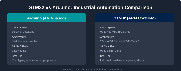
- 4. ESP32 vs STM32 I2C: Key Differences
- 5. Common I2C Problems and Fixes
- 6. Debugging I2C with Logic Analyzers
- 7. Advanced: Clock Stretching, Level Shifting and Bus Extenders
- 8. Frequently Asked Questions
- 9. Related Reading
- 10. Sources
1. What Is I2C and How Does It Work?
I2C (Inter-Integrated Circuit) is a synchronous, two-wire serial communication protocol invented by Philips Semiconductor in 1982. It allows one or more master devices to communicate with multiple slave devices over a shared bus using just two signal lines: SDA (Serial Data) and SCL (Serial Clock).
The protocol is designed for short-distance communication between chips on the same PCB or between nearby modules. Every I2C device has a unique 7-bit address (0x08 to 0x77 for most devices), which the master uses to select which slave it wants to talk to. All other devices on the bus ignore the transaction.
I2C Signal Flow
A typical I2C transaction follows this sequence:
- Start condition: Master pulls SDA low while SCL stays high
- Address byte: Master sends 7-bit address + Read/Write bit (0 = write, 1 = read)
- ACK/NACK: Slave acknowledges by pulling SDA low (ACK) or leaves it high (NACK)
- Data bytes: One or more bytes transferred, each followed by ACK/NACK
- Stop condition: Master releases SDA high while SCL is high
I2C Speed Modes
| Mode | Speed | Max Bus Length | Use Case |
|---|---|---|---|
| Standard Mode | 100 kHz | 1–2 meters | Most sensor projects |
| Fast Mode | 400 kHz | 30 cm | High-speed sensor reading |
| Fast Mode Plus | 1 MHz | Short traces | High-throughput peripherals |
| High-Speed Mode | 3.4 MHz | Very short | Display controllers, camera modules |
For most embedded projects, Standard Mode (100 kHz) or Fast Mode (400 kHz) is sufficient. Higher speeds increase noise sensitivity — keep I2C wires short and use proper pull-up resistor values.
2. Wiring: SDA, SCL and Pull-Up Resistors
Proper wiring is critical for reliable I2C communication. The two most common wiring mistakes — swapped SDA/SCL and missing pull-ups — account for the majority of I2C failures.
The Pull-Up Resistor Rule
I2C uses open-drain outputs. Devices can only pull the bus low — they cannot drive it high. Both SDA and SCL lines need pull-up resistors to hold the lines high when no device is pulling them low.
| Bus Speed | Recommended Pull-Up | Notes |
|---|---|---|
| 100 kHz (Standard) | 4.7 kΩ | Default choice for most projects |
| 400 kHz (Fast) | 2.2–4.7 kΩ | Lower value for faster speeds |
| Fast Mode Plus | 1.0–2.2 kΩ | Minimum resistance for PM+ |
Critical: Never omit pull-up resistors — I2C will not function without them. Use ceramic or film capacitors for high-frequency applications.
3. I2C Addressing: 7-bit vs 8-bit
Every I2C device has a unique address. The 7-bit address range is 0x00 to 0x7F, but certain addresses are reserved:
- 0x00: Calling address (general call)
- 0x01: Reserved
- 0x02–0x07: 10-bit addressing variants
- 0x3F–0x3F: Specific device addresses
- 0x7F: General call broadcast
The 8-bit address format is: (7-bit address << 1) | R/W
Common I2C device addresses:
- 0x27: Most I2C LCD displays
- 0x40–0x4F: GPIO expanders (e.g., PCF8574)
- 0x50–0x5F: EEPROM memory (e.g., 24LC256)
- 0x68: Real-time clocks (e.g., DS3231)
- 0x76–0x77: Pressure sensors (e.g., BMP280, BMP180)
- 0x7C: 128-byte TWI EEPROM
4. ESP32 vs STM32 I2C: Key Differences
| Aspect | ESP32 | STM32 |
|---|---|---|
| I2C Hardware | Two I2C controllers (I2C0, I2C1) | Multiple I2C interfaces (I2C1–I2C6 depending on chip) |
| Voltage Levels | 3.3V logic | 3.3V or 5V tolerant depending on series |
| Standard GPIO Pins | GPIO21 (SDA), GPIO22 (SCL) | Varies by pin map (PB9, PB10, PB7, PB6, etc.) |
| Library API | Wire.begin() |
I2C_HandleTypeDef + HAL_I2C_Init() |
| Pull-Up Resistors | External required | External required |
| Clock Stretching | Supported | Supported |
| DMA Support | Yes | Yes |
ESP32 I2C Example
#include "Wire.h"

void setup() {
  Wire.begin(21, 22);  // GPIO21 = SDA, GPIO22 = SCL
  Wire.beginTransmission(0x27);
  Wire.write(0x01);
  Wire.endTransmission();
}

void loop() {
  Wire.requestFrom(0x27, 1);
  if (Wire.available()) {
    char c = Wire.read();
  }
  delay(1000);
}
STM32 I2C Example
#include "stm32f4xx_hal.h"

I2C_HandleTypeDef hi2c1;

void SystemClock_Config(void);
static void MX_I2C1_Init(void);

int main(void)
{
  HAL_Init();
  SystemClock_Config();
  MX_I2C1_Init();

  uint8_t data = 0x01;
  HAL_I2C_Master_Transmit(&hi2c1, 0x27 << 1, &data, 1, 1000);

  uint8_t received;
  HAL_I2C_Master_Receive(&hi2c1, 0x27 << 1, &received, 1, 1000);

  while (1) {}
}

static void MX_I2C1_Init(void)
{
  hi2c1.Instance = I2C1;
  hi2c1.Init.ClockSpeed = 100000;  // 100 kHz Standard Mode
  hi2c1.Init.DutyCycle = I2C_DUTYCYCLE_2;
  hi2c1.Init.OwnAddress1 = 0;
  hi2c1.Init.AddressingMode = I2C_ADDRESSINGMODE_7BIT;
  hi2c1.Init.DualAddressMode = I2C_DUALADDRESS_DISABLE;
  hi2c1.Init.OwnAddress2 = 0;
  hi2c1.Init.CallMode = I2C_CALLMODE_DISABLE;
  hi2c1.Init.GeneralCallMode = I2C_GENERALCALL_DISABLE;
  hi2c1.Init.NoStretchMode = I2C_NOSTRETCH_DISABLE;
  if (HAL_I2C_Init(&hi2c1) != HAL_OK)
  {
    Error_Handler();
  }
}
5. Common I2C Problems and Fixes
| Problem | Cause | Solution |
|---|---|---|
| No ACK received | Wrong address, pull-up issues | Verify address, add 4.7kΩ pull-ups |
| Garbage data | Noise on SDA/SCL | Shorten wires, add shielding, reduce speed |
| Bus stuck low | Device stuck in low state | Reset device, check for clock stretching |
| Random errors | EMI interference | Twisted pair wires, ferrite beads, shielded cable |
| Address conflict | Two devices same address | Change device address via hardware resistors |
Voltage Level Shifting
When connecting 5V devices to 3.3V systems (like ESP32/STM32 to 5V sensors):
- Use bidirectional level shifters (TXB0108, PCA9306)
- Do NOT connect 5V directly to 3.3V — damages GPIO pins
- Opto-isolators for complete isolation
6. Debugging I2C with Logic Analyzers
PC-Based Logic Analyzers
| Tool | Cost | Channels | Software |
|---|---|---|---|
| Saleae Logic | $99–$399 | 8+, 16+ | sigrok, Saleae Logic |
| ELP Logic Analyzer | $25–$50 | 2, 4 | sigrok |
| Rhyme Logic | $30–$80 | 4, 8 | sigrok |
PC-Based Logic Analyzer Setup
- Connect SDA, SCL, VCC, GND to analyzer channels
- Install sigrok or vendor software
- Set I2C protocol analyzer mode
- Capture 100ms+ of data for complete transaction view
- Use trigger on Start condition for easy navigation
Signature Analysis
A healthy I2C signature shows:
- Clean Start/Stop conditions
- Consistent ACK responses
- Stable voltage levels (no ringing)
- Proper address recognition
Malfunction signatures include:
- Missing ACK responses
- SDA changes during SCL high (glitches)
- Voltage undershoots/overshoots
- Extra pulses or noise spikes
7. Advanced: Clock Stretching, Level Shifting and Bus Extenders
Clock Stretching
Some slave devices (especially slower EEPROMs and RTCs) can hold SCL low to request more processing time before completing a transaction. The master must wait (poll SCL) until the slave releases the line.
Bus Extenders
For extended bus lengths beyond normal I2C limits:
- I2C bus buffers (e.g., PCA9600): Boost signal integrity up to 100m
- Optocoupler isolators: Provide galvanic isolation for noisy environments
- Active bus multiplexers: Select between multiple I2C buses
8. Frequently Asked Questions
Q: Why does my I2C scan find different addresses than the datasheet?
A: Verify pull-up resistor values, check for voltage mismatches, ensure correct 7-bit vs 8-bit formatting. Address conflicts from nearby devices are also common.
Q: Can I use I2C at 1MHz with standard pull-ups?
A: Possible for short traces (<5cm), but not recommended for wires. Use 1kΩ–2.2kΩ pull-ups for Fast Mode Plus and keep runs under 10cm.
Q: My I2C works on bench but fails in final product. Why?
A: EMI from other circuits, inadequate grounding, insufficient pull-up resistors, or temperature drift of component values. Re-test with full system powered.
Q: Does I2C work with long cables?
A: Not recommended for standard I2C. Use RS-485, CAN bus, or industrial I2C extenders for distances >1m.
9. Related Reading
- STM32 Bootloader Tutorial: UART DFU Firmware Update Without ST-Link
- SPI Communication Complete Guide: STM32 vs Arduino Wiring, Clock Polarity and Debugging
- STM32 Timer Interrupts for Precise Motor Timing Control
- STM32 + ESP32 Industrial IoT Gateway: Build a Reliable Edge-to-Cloud Bridge
10. Sources
- NXP Semiconductors — I2C-bus Specification and User Manual (Rev. 6, 2014)
- Espressif Systems — ESP32 Technical Reference Manual
- STMicroelectronics — RM0090: STM32F4 Reference Manual
- I2C-Bus.org — Official I2C Specification and Resources
- Texas Instruments — I2C Bus Pull-Up Resistor Calculation (SLVA704)
Key Takeaways
- I2C's 2-wire design saves PCB space but requires careful attention to pull-up resistors and signal integrity
- Always verify device addresses with a scanner sketch before writing firmware
- Clock stretching and voltage level shifting are critical for multi-voltage systems
- Logic analyzers (Saleae, sigrok) are essential for debugging persistent I2C issues
- Proper termination and shielding prevent 80% of I2C debugging headaches