Key Takeaway: Monitoring tool wear in real time using spindle power data, acoustic sensors, or force measurement can prevent catastrophic tool failure, reduce scrap rates, and extend tool life by 20-40% through timely replacement decisions.
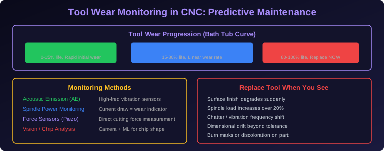
Table of Contents
1. Why Tool Wear Monitoring Matters
In CNC machining, tool wear is inevitable. Every cutting operation gradually degrades the cutting edge through abrasion, adhesion, diffusion, and chemical reactions between the tool material and the workpiece. The critical question is not whether the tool will wear, but when you should replace it. Replace too early, and you waste tool life and machine time. Replace too late, and you risk scrapped parts, spindle damage, and even operator safety hazards from broken tooling.
The economic impact of tool wear monitoring is substantial. A typical CNC machining operation spends 5-15% of total production cost on cutting tools. In precision manufacturing, the cost of a single scrapped part due to tool failure can exceed the cost of an entire set of tools. By implementing real-time tool wear monitoring, manufacturers can optimize tool change intervals, reduce scrap rates by 30-50%, and extend tool life by 20-40% compared to time-based or usage-based replacement schedules.
For small shops and hobby CNC operators, tool wear monitoring may seem like an industrial-only concern. However, even a basic spindle power monitoring setup can provide valuable information about tool condition, especially when machining expensive materials where a single tool failure means a ruined workpiece worth hundreds of dollars in material and machine time.
2. Understanding Tool Wear Stages
Tool wear follows a predictable three-stage pattern known as the bath tub curve, and understanding these stages is essential for setting up effective monitoring.
Stage 1 — Break-in wear (0-15% of tool life): When a new cutting tool is first used, the sharpest microscopic features of the cutting edge wear rapidly. This initial break-in period is normal and expected. The wear rate is high but decreasing. During this stage, surface finish may vary slightly as the edge stabilizes. Do not change the tool during break-in unless you observe abnormal behavior like excessive vibration or burning.
Stage 2 — Steady-state wear (15-80% of tool life): This is the productive phase where wear progresses linearly and predictably. The cutting edge has stabilized, and wear increases at a constant rate proportional to cutting distance or time. Surface finish remains consistent, cutting forces are stable, and dimensional accuracy is maintained. This stage represents the majority of the tool’s useful life, and your monitoring system should track the wear rate during this phase to predict when Stage 3 will begin.
Stage 3 — Accelerated wear (80-100% of tool life): Once wear reaches a critical threshold, the degradation accelerates rapidly. The cutting edge is now damaged enough that it generates significantly more heat and cutting force. Surface finish deteriorates rapidly, dimensional accuracy drifts beyond tolerance, and the risk of catastrophic tool failure increases exponentially. This is the danger zone — if your monitoring system detects the transition from Stage 2 to Stage 3, it should trigger an immediate tool change alert.
3. Monitoring Methods and Sensors
Several monitoring technologies are available, ranging from simple and inexpensive to complex and industrial-grade. The choice depends on your budget, machining requirements, and the value of the parts being produced.
Acoustic emission (AE) sensors detect high-frequency stress waves generated by plastic deformation, crack propagation, and friction at the cutting zone. AE sensors are extremely sensitive to changes in tool condition and can detect micro-cracks in the cutting edge before they propagate to failure. However, AE signals are sensitive to environmental noise and require careful calibration. Piezoelectric AE sensors cost $200-500 and mount directly on the spindle housing or workpiece fixture.
Spindle power monitoring measures the electrical current drawn by the spindle motor, which correlates directly with cutting force and thus tool condition. This is the most accessible method because many CNC controllers and VFDs already monitor spindle current. As the tool wears, the cutting force increases, which increases the spindle power draw. A 15-20% increase in spindle power above the baseline for a given operation typically indicates the tool should be replaced. This method requires no additional sensors if your VFD or controller already reports spindle current.
Force sensors (piezoelectric dynamometers) directly measure cutting forces in three axes (Fx, Fy, Fz). These provide the most accurate and direct measurement of tool condition but are expensive ($2,000-10,000 for a precision dynamometer) and typically reserved for research applications and high-value production environments. The Kistler Type 9255B is an industry standard for cutting force measurement in CNC research.
Vibration sensors (accelerometers) measure the vibration signature of the machining process. As a tool wears, the vibration frequency spectrum changes — particularly the amplitude of chatter frequencies and the harmonics of the tooth passing frequency. MEMS accelerometers costing $10-50 can be mounted on the spindle housing and connected to a microcontroller for real-time vibration analysis. Fast Fourier Transform (FFT) analysis of the vibration signal can reveal tool wear patterns that are invisible in time-domain signals.
Vision and chip analysis uses cameras and machine learning to analyze chip formation, surface finish, or the tool itself. While powerful in laboratory settings, vision-based monitoring is less practical for production environments due to coolant, chips, and lighting variability. However, for dry machining applications like wood routing or plastic milling, a camera system can provide valuable visual feedback on tool condition.
4. Spindle Power Monitoring: The Most Accessible Method
For most CNC operators, spindle power monitoring offers the best balance of cost, simplicity, and effectiveness. Here is how to implement it.
Step 1: Establish a baseline. Run a known operation with a new tool and record the spindle power at steady state. For example, a facing cut in aluminum at 10,000 RPM, 0.5mm depth, and 1000mm/min feed might draw 350W from the spindle. Record this baseline value and the operating parameters (RPM, depth of cut, feed rate, material).
Step 2: Monitor power during production. Use your VFD’s current display, a clamp-on current sensor, or your CNC controller’s power monitoring to track spindle power during each operation. The power should remain close to the baseline throughout the tool’s life.
Step 3: Set warning and alarm thresholds. A 10% increase above baseline is a warning — the tool is wearing and should be checked soon. A 20% increase is an alarm — replace the tool immediately. A 30% or greater increase indicates the tool is in the accelerated wear zone and continued machining risks part damage or tool breakage.
Step 4: Account for process variations. Spindle power varies with depth of cut, feed rate, material hardness, and coolant flow. Your monitoring system must normalize power readings against these variables. The simplest approach is to only compare power readings when the operating parameters match the baseline conditions. More sophisticated systems use a power model that predicts expected power for any set of parameters and alerts when actual power exceeds the prediction by more than a threshold.
5. Implementing Tool Wear Monitoring on Your CNC
For a hobby or small-shop CNC setup, here is a practical implementation using off-the-shelf components.
Arduino-based spindle power monitor: Connect a non-invasive current sensor like the SCT-013-000 to an Arduino with an ADC shield. The SCT-013 clips around one of the spindle motor’s power wires and outputs an analog signal proportional to the current. The Arduino samples this signal at 1 kHz, calculates the RMS current, and converts it to power using the known supply voltage and power factor. Log the power data to an SD card or transmit it via USB to a PC running monitoring software.
Software for data logging and analysis: A Python script running on a connected PC can receive the serial data from the Arduino, plot real-time power graphs, and calculate statistics like mean power, standard deviation, and trend slope. The trend slope is particularly useful — a positive slope indicates progressive wear, while a sudden jump indicates tool damage or a process upset. Libraries like matplotlib for plotting and scipy for signal processing make this a straightforward weekend project.
Integration with CNC controller: For more advanced setups, connect the power monitor to your CNC controller’s auxiliary input. LinuxCNC supports custom HAL components that can read external sensor data and use it to trigger machine actions — such as pausing the program when power exceeds the threshold, or logging the power data against the G-code line numbers for post-process analysis.
6. Industry Applications and ROI
In automotive manufacturing, tool wear monitoring is standard practice on high-volume production lines. A single tool failure on a CNC lathe turning engine blocks can cost $5,000-20,000 in scrapped material and machine downtime. The ROI on a $5,000 monitoring system is typically recovered within months through reduced scrap and extended tool life.
In aerospace machining, where parts are made from expensive materials like titanium and Inconel, tool wear monitoring is critical. A single titanium aerospace component can have a material cost of $500-5,000 and require 2-4 hours of machining time. Tool failure at the end of a long cycle means losing both the material and the machine time. Aerospace manufacturers typically use multi-sensor monitoring systems combining spindle power, vibration, and acoustic emission for maximum reliability.
For small shops, the simplest ROI calculation is: cost of one scrapped part (material + machine time + labor) versus cost of a basic monitoring system. If you machine parts worth $100 or more and experience even one tool-failure-related scrap event per month, a $200-500 monitoring setup pays for itself quickly while also extending tool life and reducing downtime.
Frequently Asked Questions
How accurate is spindle power monitoring for detecting tool wear?
Spindle power monitoring is effective for detecting moderate to severe wear, typically catching the transition from Stage 2 to Stage 3 wear reliably. It is less sensitive to early-stage micro-wear compared to acoustic emission or vibration analysis. For most production applications, a 15-20% power increase threshold provides adequate warning before tool failure. For critical applications requiring early wear detection, combine spindle power monitoring with vibration sensing for complementary coverage.
Can I add tool wear monitoring to an existing CNC machine?
Yes, spindle power monitoring can be added to virtually any CNC machine that has a VFD-controlled spindle. The most common approach is a non-invasive current sensor clamped around the spindle motor power wire, connected to a microcontroller for data logging and analysis. The total hardware cost is under $100 for a basic setup. More sophisticated implementations may require sensor mounts, signal conditioning electronics, and custom software, but the fundamental approach is the same.
What is the difference between tool wear and tool breakage?
Tool wear is a gradual, progressive degradation of the cutting edge that happens over many cuts. Tool breakage is a sudden, catastrophic failure where the tool snaps or a cutting edge chips off entirely. Monitoring systems can detect both — wear through trend analysis of gradually increasing power or vibration, and breakage through sudden step changes in the signal. Breakage detection is simpler and faster; wear detection requires baseline calibration and statistical analysis of trends over time.
How often should I calibrate my tool wear monitoring system?
Recalibrate the baseline whenever you change cutting parameters (speed, feed, depth of cut), switch to a different material, install new tooling with different specifications, or after any machine maintenance that affects spindle performance. In a production environment, running a baseline cut with a new tool at the start of each shift or each job is good practice. The calibration process takes 5-10 minutes and ensures your monitoring thresholds remain accurate.
Related Reading
- CNC End Mills and Tooling: Complete Guide to Flute Count, Coatings and Feeds
- CNC Preventive Maintenance Schedule: Complete Checklist for Lathes and Mills
- PID Control with Arduino: Closed-Loop Temperature and Motion Control Guide
- Profinet vs EtherCAT: Industrial Ethernet Protocols for Real-Time Automation
Sources
- ScienceDirect — A review of tool wear monitoring in CNC machining
- Kistler — Cutting Force Measurement Solutions
- Modern Machine Shop — Tool Wear Monitoring Techniques
- MDPI Machines — Real-Time Tool Wear Monitoring Using Spindle Motor Current
- Instructables — Arduino CNC Spindle Power Monitor Project
Disclosure: This post contains affiliate links. If you purchase through these links, we may earn a commission at no additional cost to you.