Key Takeaway: G-code is the universal language of CNC machines — mastering its core commands (G00, G01, G02, G03, and M-codes) lets you control every cut, move, and machine action with precision down to 0.001 mm.
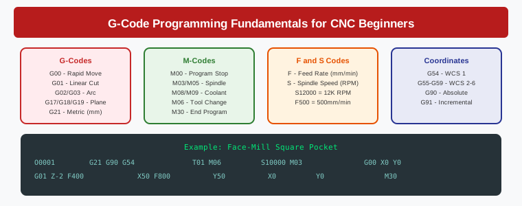
Table of Contents
- 1. What Is G-Code and Why It Matters
- 2. G-Code Line Structure: Blocks, Words, and Addresses
- 3. Essential G-Codes for Motion Control
- 4. M-Codes: Machine Function Commands
- 5. Feed Rates and Spindle Speeds
- 6. Coordinate Systems: G54–G59 Work Offsets
- 7. Writing Your First CNC Program Step by Step
- 8. Common G-Code Mistakes and How to Avoid Them
- 9. G-Code Editors and Simulation Tools
- 10. Frequently Asked Questions
- 11. Related Reading
- 12. Sources
What Is G-Code and Why It Matters
If you have ever watched a CNC router, mill, or lathe execute a complex part and wondered how the machine knows exactly where to move, the answer is G-code. Short for “Geometric Code” or “Generator Code,” G-code is a standardized programming language that tells CNC machines precisely where to position the tool, how fast to move, when to turn the spindle on or off, and which coolant settings to use.
G-code programming CNC work is the backbone of modern manufacturing. Every part you see in aerospace, automotive, medical devices, and industrial automation started as a G-code program at some point. Even when CAM software generates toolpaths automatically, the output is always G-code. Understanding this language gives you direct control over your machine and the ability to debug, modify, and optimize programs without relying entirely on a CAM post-processor.
The G-code standard was formalized under ISO 6983 and RS-274, but in practice, most controllers accept dialects with slight variations. The good news is that roughly 80 percent of any G-code program uses the same 15 to 20 core commands regardless of the machine brand. Learning these fundamentals puts you in a strong position to program virtually any CNC equipment.
G-Code Line Structure: Blocks, Words, and Addresses
Every G-code program is a sequence of lines called blocks. Each block contains one or more words, where a word is a letter followed by a numeric value. The letter is called an address and it defines what type of instruction the number represents.
The most common address letters you will encounter:
- G — Preparatory function (motion mode, plane selection, units)
- M — Miscellaneous function (spindle, coolant, program control)
- X, Y, Z — Axis positions in Cartesian coordinates
- F — Feed rate (mm/min or inches/min)
- S — Spindle speed in RPM
- T — Tool number selection
- N — Line number (optional, used for program referencing)
- P, Q, R — Parameters used within specific cycles and sub-programs
A typical block might look like this:
N010 G01 X50.0 Y25.0 F200 S12000
This single line tells the machine: move to position X50.0, Y25.0 in a straight line (G01), at a feed rate of 200 mm/min (F200), with the spindle spinning at 12,000 RPM (S12000). Understanding how to read and write these blocks is the essential first skill in G-code programming CNC work.
Essential G-Codes for Motion Control
Motion codes are the heart of any G-code program. Here are the commands you will use in virtually every file:
G00 — Rapid Positioning
G00 moves the tool as fast as the machine can travel to the target position. It is used for non-cutting moves like approaching the workpiece or retracting the tool. No material is removed during a G00 move. The feed rate is set by the machine’s rapid traverse rate, not by the F value.
G00 X10.0 Y10.0 Z5.0 (rapid to position above part)
G01 — Linear Interpolation (Straight Cut)
G01 cuts a straight line at the specified feed rate. This is your primary cutting move. The F word must be defined either in this block or in a previous block within the same motion mode.
G01 Z-2.0 F100           (plunge into material at 100 mm/min)
G01 X80.0 Y25.0 F300     (cut along X axis at 300 mm/min)
G02 — Clockwise Circular Interpolation
G02 cuts a clockwise arc. You specify the end point (X, Y) and either the center offset (I, J relative to the start point) or the radius (R). This command is essential for creating fillets, radii, and rounded features.
G02 X40.0 Y50.0 R15.0 (clockwise arc with 15mm radius)
G03 — Counter-Clockwise Circular Interpolation
G03 is the mirror of G02, cutting counter-clockwise arcs. Together, G02 and G03 give you full control over any curved geometry.
G03 X40.0 Y50.0 I-10.0 J5.0 (CCW arc using center offsets)
G90 and G91 — Absolute vs. Incremental Positioning
G90 sets absolute mode where all coordinates are relative to the program origin (G54 work offset). G91 sets incremental mode where each move is relative to the current position. Most CNC programs default to G90, and you should explicitly state it at the start of your program.
G90 (absolute mode)
G91 (incremental mode)
Other Important G-Codes
- G17 / G18 / G19 — Plane selection (XY, XZ, YZ). G17 (XY plane) is the default for most milling operations.
- G20 / G21 — Unit selection. G20 = inches, G21 = millimeters. Always declare this at program start.
- G40 / G41 / G42 — Cutter radius compensation (cancel, left, right). G41 offsets the tool left of the programmed path, G42 offsets right. Essential for finishing passes where you need exact part dimensions.
- G43 / G44 — Tool length compensation. G43 applies the tool length offset from the tool table.
- G80 — Cancel canned cycle. Returns the machine to normal motion mode.
- G81–G89 — Canned cycles for drilling, boring, tapping, and other hole-making operations. These dramatically simplify repetitive drilling patterns.
M-Codes: Machine Function Commands
M-codes control the machine’s physical functions rather than tool motion. The exact M-codes available depend on your controller (Fanuc, Siemens, LinuxCNC, Mach3), but these are universally common:
- M00 — Program stop. Pauses execution until the operator presses cycle start.
- M01 — Optional stop. Pauses only if the optional stop switch is active.
- M02 / M30 — Program end. M30 also rewinds the program to the start.
- M03 / M04 — Spindle on clockwise (M03) or counter-clockwise (M04).
- M05 — Spindle stop.
- M06 — Tool change. Executes the automatic tool change sequence.
- M08 / M09 — Coolant on (M08) and coolant off (M09).
- M07 — Mist coolant on (used in some setups for minimum quantity lubrication).
A practical example combining M-codes with motion:
M06 T01           (select tool 1)
M03 S10000        (spindle CW at 10000 RPM)
M08                (coolant on)
G43 H01 Z10.0     (apply tool 1 length offset, move to Z10)
G00 X0.0 Y0.0     (rapid to start position)
G01 Z-3.0 F80     (feed into material)
G01 X100.0 F400   (cut along X)
M09                (coolant off)
M05                (spindle stop)
G00 Z25.0          (rapid retract)
M30                (program end)
Feed Rates and Spindle Speeds
Two of the most critical parameters in any G-code program are the feed rate (F) and spindle speed (S). Getting these wrong leads to poor surface finish, excessive tool wear, or even tool breakage.
Feed rate (F) is specified in mm/min for metric or inches/min for imperial. It controls how fast the tool moves through the material during a G01, G02, or G03 move. Feed rates depend on the material being cut, the tool diameter, the depth of cut, and the desired surface finish. For aluminum with a 6mm end mill, typical feed rates range from 500 to 2000 mm/min. For steel, 100 to 400 mm/min is more common.
Spindle speed (S) is specified in RPM. It controls how fast the tool rotates. Higher RPM generally gives a better surface finish but generates more heat. The formula for calculating spindle speed is:
RPM = (Cutting Speed × 1000) / (π × Tool Diameter)
Example: (300 m/min × 1000) / (3.1416 × 6mm) = 15,915 RPM
In G-code, you set these values explicitly. Remember that G01 moves use the F value, and G00 rapid moves ignore it entirely.
Coordinate Systems: G54–G59 Work Offsets
CNC machines have a fixed machine coordinate system defined by the machine’s home position and physical limits. When you program a part, you work in a work coordinate system (WCS) that you define relative to your workpiece.
G54 through G59 define up to six work coordinate systems. G54 is the most commonly used. You set the G54 origin (X0, Y0, Z0) to a specific point on your workpiece — typically the bottom-left corner or the center — by entering offset values in the machine’s offset table.
This means your program always references the same coordinates regardless of where the part is physically clamped on the table. If you move the workpiece, you simply update the G54 offset rather than rewriting every coordinate in the program. This is a fundamental concept in production G-code programming CNC workflows where you need to run the same program across multiple setups.
Writing Your First CNC Program Step by Step
Let us walk through a complete, simple program that mills a 50mm × 50mm square pocket, 3mm deep, using a 6mm end mill on aluminum. This example demonstrates all the core concepts discussed above.
%
O0001 (SQUARE POCKET - 6MM ENDMILL)
(Stock: Aluminum 6061, 10mm thick)
(Machine: 3-axis VMC, G54 origin at bottom-left)

N010 G21 G90 G17 G40 G49 G80    (safety block: metric, abs, XY plane, cancel comp)
N020 M06 T01                    (tool change to tool 1 - 6mm carbide end mill)
N030 M03 S12000                 (spindle CW at 12000 RPM)
N040 M08                        (flood coolant on)
N050 G43 H01 Z15.0             (tool length comp, move safe above part)

(SIDE MILL THE SQUARE PROFILE)
N060 G00 X0.0 Y0.0             (rapid to corner)
N070 G01 Z-3.0 F80             (plunge to depth at 80 mm/min)
N080 G01 X50.0 F350            (cut bottom edge)
N090 G01 Y50.0                 (cut right edge)
N100 G01 X0.0                  (cut top edge)
N110 G01 Y0.0                  (cut left edge, return to start)

(RETRACT AND END)
N120 G00 Z25.0                 (rapid retract to safe height)
N130 M09                        (coolant off)
N140 M05                        (spindle stop)
N150 M30                        (program end and rewind)
%
Notice the structure. The program starts with a safety line (N010) that establishes units, motion mode, and cancels any active cycles or compensations. This prevents unexpected behavior from a previous program. The tool change and spindle start happen at safe clearance heights. Only after everything is set up does the tool approach and begin cutting. The program ends with a clean retract and machine stop.
Common G-Code Mistakes and How to Avoid Them
Forgetting the safety line: Always start with G21 G90 G17 G40 G49 G80. If the previous program left cutter compensation or a canned cycle active, your next program could crash.
Mixing G90 and G91: Accidentally leaving incremental mode active causes the machine to interpret coordinates as relative moves instead of absolute positions. This is one of the most common causes of crashes.
Not specifying units: If your program says X50.0 and you are in G20 (inches) instead of G21 (mm), the machine will travel 50 inches instead of 50 millimeters. Always declare units explicitly.
Missing feed rate on first G01: If no F value has been set before the first G01 move, some controllers will throw an error while others will use the last stored feed rate. Always include F in your first cutting move.
Rapid moves at cutting depth: A G00 move at Z-3.0 will plow the tool through the material at maximum traverse speed. Always retract with G00 to a safe Z height before any rapid XY moves.
No Z retract before tool change: M06 without first moving to a safe Z position risks a collision during the tool change. Always retract Z well above the part and fixtures before calling M06.
G-Code Editors and Simulation Tools
Before sending a program to your machine, you should always simulate it. Several free and paid tools make this easy:
- CNCCookbook G-Code Editor — A browser-based editor with syntax highlighting and basic simulation. Great for beginners writing short programs.
- LinuxCNC — A free, open-source CNC controller that includes a built-in G-code interpreter and simulator. Excellent for learning and testing programs offline.
- CAMotics — An open-source 3D G-code simulator that renders toolpaths in a virtual environment. You can see exactly what the tool will cut before running it on real material.
- NC Viewer — A web-based G-code visualizer that shows toolpath motion in 2D and 3D. Simple, fast, and useful for quick verification.
- Fusion 360 CAM — While primarily a CAM tool, its built-in post-processor output viewer lets you inspect generated G-code alongside the 3D model.
For industrial environments, most controllers (Fanuc, Siemens, Heidenhain) have built-in dry-run and single-block modes that let you execute the program one line at a time with the spindle off and feed rate overridden to minimum. Always use these features when proving out a new program on the actual machine.
Frequently Asked Questions
How long does it take to learn G-code programming for CNC machines?
Most beginners can learn the essential G-codes (G00, G01, G02, G03, G90, G91, and common M-codes) within one to two weeks of consistent practice. Writing production-quality programs for complex parts typically takes three to six months of hands-on experience. The fundamentals covered in this G-code programming CNC guide give you a strong foundation that most CAM users never develop.
Can I run a CNC machine without knowing G-code?
Yes, CAM software generates G-code automatically from 3D models. However, understanding G-code is invaluable for debugging failed programs, making quick modifications on the shop floor, and optimizing toolpaths for better surface finish or faster cycle times. Many experienced machinists write simple programs directly in G-code for jobs that do not require complex 3D geometry.
What is the difference between G-code programming CNC controllers like Fanuc and LinuxCNC?
While the core G-code commands are standardized, each controller brand implements slight variations. Fanuc uses specific sub-program calling conventions, LinuxCNC supports extended commands through its configuration language, and Siemens uses a variant called ShopTurn. The fundamental motion codes (G00–G03, G90, G91, M03–M06) remain consistent across all of them.
Is G-code being replaced by newer programming methods?
No. G-code remains the universal output format even when newer methods like conversational programming or AI-assisted CAM are used as input. Every toolpath, whether designed in SolidWorks, Fusion 360, or generated by machine learning, ultimately converts to G-code for the machine controller to execute. Understanding G-code ensures you can work with any CAM system and any CNC machine.
Related Reading
- CNC Machine Calibration: Complete Guide to Squaring, Tramming, and Backlash Compensation — Learn how proper machine calibration directly impacts the accuracy of your G-code programs.
- CNC End Mills and Tooling: Complete Guide to Flute Count, Coatings, and Feeds — Choosing the right end mill is critical when setting feed rates and spindle speeds in your G-code.
Sources
- CNCCookbook — G-Code Tutorial for CNC Programming
- LinuxCNC — G-Code Reference Documentation
- NIST — RS-274 Interpreter Standard Reference
- CAMotics — Open-Source G-Code Simulator
Affiliate Disclosure: This article may contain affiliate links. If you purchase through these links, justLast.in may earn a commission at no additional cost to you. We only recommend products and tools we genuinely use and trust in our workshop.