Key Takeaway: A well-organized Fusion 360 CAM tool library with accurate tool definitions and saved presets eliminates repeated data entry, reduces programming errors, and cuts CAM setup time by 50% or more on every job.
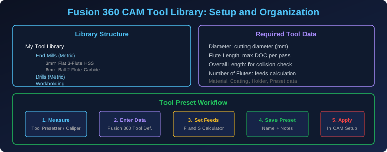
Table of Contents
1. Why a Tool Library Matters for CAM Programming
Every CAM operation starts with tool selection. The tool definition determines the cutting parameters, toolpath geometry, collision detection, and gouge prevention that the CAM kernel uses to generate safe and efficient G-code. When your tool library contains accurate, complete tool data, Fusion 360’s CAM engine can automatically calculate optimal feeds and speeds, detect potential collisions with holders and workholding, and generate toolpaths that match your real-world setup.
Without a proper tool library, you are forced to enter tool dimensions manually for every new project. This is time-consuming, error-prone, and leads to inconsistencies between programs. A missing flute length parameter means Fusion 360 cannot accurately check for holder collisions during deep pocket operations. An incorrect tool diameter causes the CAM software to generate toolpaths that cut parts oversize or undersize. These errors only become apparent after the part is machined, when they are expensive to fix.
The investment in building a comprehensive tool library pays dividends across every project. A well-maintained library with 50-100 common tools covers 90% of typical CNC operations. Once set up, adding a new project to the CAM workspace takes minutes instead of hours, and you gain confidence that the generated G-code will produce accurate parts because the tool definitions match your actual tooling.
2. Organizing Your Fusion 360 Tool Library
Fusion 360’s tool library supports a hierarchical folder structure that lets you organize tools in whatever way makes sense for your shop. The key principle is to organize by tool type first, then by size, so you can quickly find the right tool when programming a new job.
Top-level organization: Create folders for each major tool category — End Mills, Drills, Reamers, Taps, Boring Bars, Face Mills, and Special Purpose tools. Within each category, create sub-folders for metric and imperial sizes if you work with both measurement systems. This prevents accidental metric/imperial mix-ups that can produce parts machined to the wrong scale.
Sub-category structure for end mills: Under the End Mills folder, consider organizing by flute count (2-flute, 3-flute, 4-flute), then by material (HSS, Carbide, Coated Carbide). For shops that do both aluminum and steel work, this structure makes it easy to find the right end mill for each material. A 3-flute carbide end mill with ZrN coating is ideal for aluminum, while a 4-flute carbide end mill with TiAlN coating performs better in steel.
Naming conventions: Use a consistent naming convention for every tool. Include the tool type, diameter, flute count, material, and coating in the name. For example: “6mm 3-Flute Carbide ZrN End Mill” tells you everything you need to know at a glance. Avoid cryptic names like “EM01” that require a separate reference chart to decode.
Sharing across projects: Fusion 360’s tool library can be shared across projects and with team members. Create a cloud-based library that all CAM programmers in your shop access, ensuring everyone uses the same tool definitions and cutting parameters. This consistency is particularly important in production environments where multiple programmers may work on the same parts.
3. Required Tool Data: What to Enter and Why
Fusion 360’s tool definition dialog has numerous fields, but not all are equally important. Here are the fields that directly affect CAM accuracy and safety, and what each one does.
Diameter (cutting diameter): This is the most critical dimension. Fusion 360 uses the tool diameter to calculate the offset between the toolpath and the finished part geometry. An error in diameter directly translates to an error in part dimensions. Measure the cutting diameter with a micrometer or caliper — do not rely on the nominal size printed on the tool packaging, which may differ from the actual size by several tenths of a millimeter.
Flute length: This determines the maximum depth of cut per pass and is critical for collision detection. If your flute length is 25mm and you try to cut a 30mm deep pocket in a single pass, the tool holder will collide with the workpiece. Fusion 360 uses the flute length to automatically limit the depth of cut and to flag potential holder collisions in the simulation.
Overall length: Used for collision detection between the tool holder and the workpiece or fixture. When programming deep pocket operations or machining near tall fixtures, accurate overall length data prevents catastrophic collisions that can damage the spindle, break the tool, and destroy the workpiece.
Number of flutes: This parameter directly affects feed rate calculations. The chip load per tooth is calculated as feed rate divided by (RPM times number of flutes). Using the wrong flute count produces incorrect chip loads, leading to either too light a cut (rubbing and heat buildup) or too heavy a cut (tool overload and potential breakage).
Tool material and coating: While these do not directly affect toolpath geometry, they influence the feeds and speeds calculator’s recommendations. HSS tools require lower cutting speeds than carbide tools, and coated tools can tolerate higher speeds than uncoated tools. Entering this data correctly ensures the calculator provides realistic starting points for your cutting parameters.
Holder type and dimensions: For accurate collision simulation, enter the holder dimensions — at minimum the holder diameter and the distance from the tool tip to the holder bottom. Fusion 360’s tool simulation uses this data to check for holder-workpiece interference during complex 5-axis operations.
4. Creating and Managing Tool Presets
A tool preset in Fusion 360 captures a complete set of cutting parameters — feeds, speeds, coolant settings, and stepover/stepdown values — for a specific material and operation type. Presets are what transform a tool definition from a static dimension entry into a reusable CAM building block.
Creating a preset: After defining a tool’s physical dimensions, click the Presets tab in the tool definition dialog. Create a new preset with a descriptive name like “Aluminum – Roughing” or “Steel – Finishing.” Enter the recommended spindle speed, feed rate, plunge feed rate, stepover, and stepdown for that specific material and operation. Save the preset, and it will be available every time you select this tool in any CAM operation.
Multiple presets per tool: A single tool can have dozens of presets for different materials and operation types. A 6mm carbide end mill might have presets for aluminum roughing (24,000 RPM, 3000mm/min), aluminum finishing (24,000 RPM, 1500mm/min), mild steel roughing (8000 RPM, 800mm/min), and stainless steel finishing (6000 RPM, 400mm/min). When you select the tool in a CAM operation, you simply choose the appropriate preset instead of entering parameters from scratch.
Measuring actual tool dimensions: Before saving presets, measure the actual tool dimensions with precision instruments. Use a micrometer for diameter measurement, a tool presetter or height gauge for flute length and overall length, and a loupe or microscope to count flutes accurately. Record the measured values in the tool definition — this is the single most important step in creating a reliable tool library.
5. Feeds and Speeds Calculator Integration
Fusion 360 includes a built-in feeds and speeds calculator that uses the tool definition data plus workpiece material properties to recommend cutting parameters. Understanding how this calculator works helps you create better presets and validate the recommendations against your experience.
How the calculator works: The calculator uses the tool’s diameter, number of flutes, material, and coating to determine the recommended surface speed (SFM or m/min). It then calculates RPM from the surface speed and diameter. The feed rate is calculated from the recommended chip load per tooth, RPM, and number of flutes. Stepover and stepdown are recommended based on the tool’s flute length and cutting geometry.
Validating recommendations: The calculator provides excellent starting points, but real-world conditions may require adjustments. Factors like machine rigidity, workpiece clamping, coolant type, and tool holder runout all affect the optimal parameters. Use the calculator’s recommendations as a baseline, then adjust based on the sound of the cut, the chip formation, and the surface finish quality. Save the adjusted values as a new preset so you capture the proven parameters for future use.
Material database: Fusion 360’s material library includes hundreds of workpiece materials with their specific cutting properties. Selecting the correct material in the CAM setup ensures the feeds and speeds calculator uses the right surface speed and chip load values. If your material is not in the library, you can create custom materials with user-defined cutting properties.
6. Workholding Templates in the Library
Fusion 360’s CAM tool library supports workholding definitions — vise models, fixture plates, clamps, and custom workholding devices — that can be imported into any project. This feature is particularly valuable for shops that use standardized workholding setups.
Vise models: Import your vise as a 3D model and define its jaw opening range, jaw width, and soft jaw location. When you set up a CAM operation, selecting the vise from the library automatically positions the workpiece reference point at the correct location relative to the vise jaws. This eliminates manual coordinate calculations and ensures consistent part alignment across programs.
Fixture plates: For shops using modular fixture plates with a grid of threaded holes, import the plate model and define the hole pattern. The CAM simulation then checks for collisions between the tool, holder, and fixture plate throughout the entire toolpath, preventing expensive mistakes when machining near the fixture.
Custom workholding: Many shops develop custom fixtures, soft jaws, and workholding devices for their most common parts. Modeling these in Fusion 360 and saving them to the library means you only need to model the fixture once. Future programs can import the fixture and automatically set up the workpiece position and collision boundaries.
Frequently Asked Questions
How many tools should be in a starter tool library?
A functional starter library needs approximately 20-30 tools covering the most common operations. This includes 5-8 end mills in common sizes (3mm, 6mm, 8mm, 10mm, 12mm in both flat and ball profiles), 5-8 drills in standard sizes, a face mill, a chamfer tool, and a few specialty tools. This set covers 90% of typical CNC work. You can expand the library over time as you acquire new tools and encounter new machining requirements.
Can I import tool data from a manufacturer’s catalog?
Yes, Fusion 360 supports importing tool data from several formats including Fusion 360 library files, CSV files, and some manufacturer-specific formats. Many tool manufacturers like Harvey Tool, Helical Solutions, and Amana provide downloadable tool libraries for Fusion 360 that include all dimensions and recommended cutting parameters. Importing these saves significant time compared to manual entry.
How do I share my tool library with other CAM programmers?
Fusion 360’s tool libraries are stored in the cloud and can be shared with other users who have Fusion 360 access. Right-click on the library in the Tool Library panel and select “Share” to invite collaborators. Shared libraries update in real time, so when one programmer adds a new tool or updates a preset, all users see the changes immediately. This ensures consistency across the entire CAM team.
What happens if my tool dimensions change over time?
Tools wear, get reground, or are replaced with slightly different models from different manufacturers. When you notice a tool’s actual dimensions differ from the library entry, update the tool definition with the measured values and create a new preset. Version history in Fusion 360 allows you to roll back changes if needed. For reground tools, create a new tool entry with “Reground” in the name rather than modifying the original, so you maintain a record of the original tool specifications.
Related Reading
- SolidWorks CAM vs Mastercam: Professional CAM Software for CNC Programming
- CNC End Mills and Tooling: Complete Guide to Flute Count, Coatings and Feeds
- CNC Machine Calibration: Complete Guide to Squaring, Tramming and Backlash Compensation
- Complete Guide to CNC Milling Operations: Face, Slot, Contour and Pocket Milling
Sources
- Autodesk Fusion 360 — Tool Library Documentation
- Helical Solutions — Downloadable Fusion 360 Tool Libraries
- Harvey Performance — Cutting Tool Data for Fusion 360
- CNCCookbook — Feeds and Speeds Calculator Guide
- YouTube — Fusion 360 Tool Library Setup Tutorial
Disclosure: This post contains affiliate links. If you purchase through these links, we may earn a commission at no additional cost to you.