CNC Lathe Retrofit: Step-by-Step Guide for Old CNC Lathes
Key Takeaway
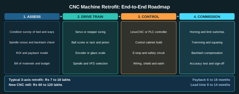
A cnc lathe retrofit goes wrong when stages are overlapped, so the working rule is to strip and measure everything before replacing anything, and to close each stage with a written measurement before the next one starts. The measurement you take while the machine is apart is the only baseline you will ever get.
Figure 1: The eight-stage CNC lathe retrofit sequence and the check that closes each stage
Table of Contents
- 1. Before You Start: Is This Lathe a Candidate?
- 2. Stage 1 and 2: Baseline and Strip
- 3. Stage 3 and 4: The Drive Train and the Spindle
- 4. Stage 5 and 6: Mounting, Wiring and Homing
- 5. Stage 7 and 8: Tramming, Compensation and Acceptance
- 6. The Mistakes That Ruin Lathe Retrofits
- Related Reading
- Sources
1. Before You Start: Is This Lathe a Candidate?
A lathe retrofit is a re-sequencing of work, not a rebuild. This guide walks through the whole job in eight stages – baseline, strip, drive train, spindle, mounting, wiring, homing, geometry and acceptance – with the check that closes each stage, because the stages that get skipped are the ones that decide whether the machine can be guaranteed. The sections give the measurements, the costs in rupees, and the mistakes that ruin projects.
A cnc lathe retrofit is a different job from a mill retrofit in one important way: the lathe’s spindle, taper, chuck and bearing set are a matched system, and the tailstock is a second axis that either gets a drive or does not. Both of those facts push the cost up relative to a mill retrofit of the same size.
The candidate checklist
- Bed and ways. A lathe bed is a long cast iron or fabricated structure carrying the saddle and the tailstock. Check for cracks, check the bed ways for pitting, and check the saddle and tailstock ways. A lathe bed that has been sitting with the coolant running down it is the most common source of hidden corrosion.
- Beads or guideways. Modern lathes have replaceable linear wayways; older ones have flat ways with gib strips. Flat ways can be scraped and re-gibbed. Linear wayways that have been contaminated are often a replacement item.
- Spindle. Check the taper for rust, steps and ovality. Check the bearing noise. A spindle that was already noisy before the retrofit will be noisy after it, and it will be blamed on the retrofit.
- Tailstock. Decide now whether the tailstock becomes a servo axis or stays a manual quill. This decision changes the budget by Rs 60,000 to Rs 1.2 lakhs and changes the electrical design.
- Existing control. Fanuc 0T, 0M, Siemens 802, and older systems are all replaceable. The salvaged servo motors from a Fanuc 0T are sometimes worth reusing, but only after they are tested for insulation resistance and bearing condition.
If the spindle taper is BT30 on a machine that has to hold 10 micron on a 50 mm diameter part, the spindle rebuild is not optional. If the taper is in good condition and the bearings are quiet, spend the budget on the axes instead.
Know which lathe you are building
| Lathe type | Axes | Retrofit cost (Rs lakhs) | Typical use |
|---|---|---|---|
| 2-axis turning (Z, X) | 2 | 4.5 to 9 | Simple turning and facing, no live tooling |
| 3-axis with live tooling | Z, X, C or Y | 7 to 13 | Milling on the face, cross drilling |
| 3-axis with servo tailstock | Z, X, plus driven tailstock | 8 to 15 | Long bar work, steady rest support |
| Y-axis with sub-spindle | Z, X, Y | 14 to 22 | Live tooling, mill turn, bar feeding |
Everything in this guide applies to all four. The stages do not change; the axis count does.
Section summary. The first question in cnc lathe retrofit is not technical: is this machine a candidate at all. A sound bed, clean ways, a taper worth keeping and a decision made early about the tailstock are the things that determine the budget. Spending an afternoon on this assessment is what separates a cnc lathe retrofit that lands inside its estimate from one that overruns by half.
Budget a cnc lathe retrofit at 4.5 to 22 lakhs depending on the axis count, and hold that range in your head from the survey stage onwards.
2. Stage 1 and 2: Baseline and Strip
These two stages are the ones that get skipped, and they are the two that make the difference between a retrofit you can prove and a retrofit you hope works.
Stage 1: baseline measurement, before anything is touched
Record these numbers, in writing, with photographs, before a single screw is removed:
- Spindle nose runout. Mount a dial indicator on the spindle nose, at the chuck flange or the taper face, and rotate the spindle by hand through one full turn. Record total indicator reading. Write it as “TIR at nose”. Do not write “runout” and leave it there: runout at the nose, at the chuck register and at the tool tip are three different numbers.
- Axis backlash. On the Z axis, engage the leadscrew or ballscrew to the saddle, attach a spring scale to the saddle and pull it in one direction, then push it the other way. Record the force difference. The force converts to backlash by dividing by the screw stiffness; the stiffness is the axial stiffness of the screw and supports. For a 4000 N/mm screw (a typical 2508 ballscrew), a 10 N difference corresponds to 10 / 4000 = 0.0025 mm. If the dial indicator shows more, the screw is bent or the supports are loose, not the screw worn.
- Way flatness and saddle squareness. Blue the bed ways and slide the saddle along them; check for a bow. Put a straightedge across the carriage and the tailstock and check the gap with feelers or a wedge.
- Tailstock alignment. Check the tailstock centreline against the spindle centreline with a dial indicator mounted in the tailstock quill.
- Existing electrical state. Insulation resistance of the motors, earthing continuity, and the state of the cable tray.
These baselines are how you prove the retrofit worked. Without them, a claim that the machine “feels better” is not evidence.
Stage 2: strip
Remove the old control cabinet, the old drives, the motors, the feedback devices, the wiring and the conduits, and the power supply distribution. Photograph every connector before it comes off, and label every wire that stays. Tag and bag the parts that might be reused: servo motors, ball screws, limit switches, the chuck, the tailstock quill assembly.
Two rules here. First, do not throw away the old ball screws until the new ones are fitted and measured. If the retrofit runs late, having a known-good set of screws with known backlash is worth more than the money you saved by not keeping them. Second, do not reuse the old cable for the new drives. The old cable is sized for the old motors and often has multi-core control wiring that is unsuitable for a servo motor cable. Motor cables are cheap relative to the fault they prevent.
Section summary. The baseline and strip stages are the two that get skipped, and they are the two that make the difference between a retrofit you can prove and one you hope works. Every number you record while the machine is apart is the only baseline you will ever have, and it is the only evidence you will have when the acceptance test is argued over. Keep the old ball screws until the new ones are measured.
Record every baseline number in a single sheet, because the acceptance test at the end of a cnc lathe retrofit is compared against those numbers and nothing else.
3. Stage 3 and 4: The Drive Train and the Spindle
This is where the money goes and where the quality of the retrofit is decided.
Stage 3: measure the screw before replacing it
Measure, do not assume. On the Z axis of a lathe the screw is usually the largest and the most heavily loaded, and it is also the one most likely to be a wear item in an old machine.
The decision rule: if the backlash is under 0.03 mm and the screw is not bent (checked with a dial indicator against the screw nut with the screw supported), the screw can usually be kept and re-preloaded. If the backlash is above 0.03 mm, or if the screw is bent, replace it.
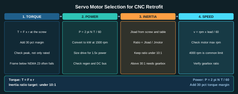
Choosing the replacement lead is a real decision, not a default. A 10 mm lead gives a higher feed rate for a given rpm, but a higher thrust requirement at the same force. The thrust needed comes from the axial cutting force divided by the screw efficiency: F = 2 pi eta T / lead. A 2000 N axial cutting force on a 10 mm lead with 0.9 efficiency needs a torque of 2000 x 0.010 / (2 x 3.1416 x 0.9) = 3.54 Nm at the screw. On a 5 mm lead the same force needs 7.07 Nm. Doubling the lead roughly halves the motor torque requirement but also doubles the thrust per motor Newton, so the bearing rating and the screw diameter must be checked together. The full selection method is in the screw drive comparison.
Stage 4: the spindle
Order this work in the right sequence, because each step depends on the previous one:
- Remove the chuck and check the taper bore with a bore gauge or a good radius gauge. Look for ovality and for the step that a worn bearing produces on the taper face.
- Inspect the spindle bearings. On a lathe this usually means removing the spindle or the front bearing housing, which is labour-intensive, so plan for a day of shop time.
- Replace the angular contact bearing set with a matched set, and set the preload correctly. The preload method and the failure modes are in the spindle rebuild guide.
- Clean the taper, apply a thin film of spindle oil and refit the chuck. Never run a chuck on a dry taper; it scores the bore and then the runout problem is permanent.
- Measure the nose runout again. It should be at or below the number you recorded in stage 1, and ideally much better.
Then the drive. A spindle VFD is sized by the motor, and the motor is sized by the work. For a lathe doing general turning in steel, a 5.5 to 7.5 kW motor with a 7.5 kW VFD is the common choice; for a light duty aluminium or brass job, 2.2 to 3.7 kW is enough. The VFD sizing arithmetic, the cable rules and the parameter setup are in the spindle VFD guide.
One lathe-specific point: if you want constant surface speed, which you should, the control needs the spindle to be a controlled axis with a feedback value, not just a VFD with a frequency command. A VFD with an analogue speed reference gives you an approximate speed that drifts with load. If the machine needs real constant surface speed, use a spindle with a tachometer or encoder feedback and a control that reads it.
Section summary. The drive train and the spindle are where the money goes and where the quality of cnc lathe retrofit is decided. The rule is to measure the screw before replacing it, to pick the lead from a real thrust calculation rather than a default, and to work on the spindle in a fixed order so that each step depends on the previous one. A lathe spindle taper, chuck and bearing set are a matched system, not three separate purchases.
A lathe axis conversion is the same calculation as on a mill, and the screw drive comparison covers the thrust arithmetic in full.
4. Stage 5 and 6: Mounting, Wiring and Homing
Order of work in this stage: mechanical mounting first, then electrical, then homing. If you wire before mounting, the cable lengths will be wrong.
Stage 5: mount the motors
Use rigid couplings with a spacer section, and keep the motor clear of the oil and the coolant. On a lathe, the X axis motor is often mounted under the saddle and the Z axis motor at the rear of the bed, so both need a bracket that is stiff and that can be shimmed for alignment. Align the coupling so the motor shaft and the screw are coaxial within 0.02 mm runout, and check again after the base bolts are tightened.
Do not use a flexible jaw coupling as the primary connection between a servo and a screw on a retrofit. A jaw coupling introduces a torsional spring that shows up as a settling time problem and as a lost step under rapid direction reversal. A rigid coupling with a spacer is better, and the alignment is easier to verify with a dial indicator. If a flexible element is needed for a specific reason, use a bellows-type element with a high torsional stiffness, not a jaw coupling.
Stage 6: wire the drives
- Motor power: screened cable, both ends bonded to the cabinet earth and the motor earth.
- Encoder feedback: use the shielded feedback cable that came with the drive, keep it out of the power cable bundle, and do not splice it. A spliced encoder cable is the number one cause of an encoder fault that appears only when the drive warms up.
- Motor cables and signal cables in separate trays, and never parallel for more than a short distance.
- Earth straps short and wide. A 20 mm wide braided strap is worth more than a 2 m long 6 mm^2 earth conductor.
Homing on a lathe
A lathe home is more involved than a mill home because there are more things that must be at a known position. At minimum:
- Z home at the end of travel, referencing off a limit switch or an inductive sensor on a flag.
- X home at the centre or at a defined diameter, again referenced to a flag.
- Turret index reference so the control knows where tool pocket 1 is. Without this the tool changer position is unknown and every tool offset is suspect.
- Tailstock position if the tailstock is motorised.
Use a two-stage homing move: move fast toward the flag at a speed the machine can stop from, back off by a fixed distance, then approach again at a slow creep speed. The second approach is what makes the home position repeatable; the first approach is only what makes it fast. The limit and sensor selection, the common wiring failures and the difference between a hard limit and a home switch are covered in the limits and homing guide.
Section summary. Mounting, wiring and homing have to happen in that order, and on a lathe the homing job is larger than on a mill because there is more that must be at a known position. The turret index reference and the tool offsets are different values and both are required. A two-stage homing move is what makes the reference repeatable, and the wiring rules are what stop an intermittent encoder fault at temperature.
Spending two days on the mounting and wiring of a cnc lathe retrofit is cheaper than the week of rework that a wrong coupling or a spliced encoder cable causes.
5. Stage 7 and 8: Tramming, Compensation and Acceptance
The machine is not finished when the axes move. It is finished when it holds a tolerance under load.
Stage 7: geometry
- Tram the X axis. Set the spindle centreline parallel to the bed ways, within 0.01 mm per 300 mm. Use a dial indicator on a bar mounted in the spindle, and adjust the motor mount, not the screw.
- Square the tailstock. Use a test bar between the spindle centre and the tailstock centre; the reading must be identical in three positions along the bar.
- Set the backlash compensation in both directions on each axis, and verify it by running the same cut repeatedly and measuring. Backlash compensation on a retrofit is often set once and never re-verified, and the screw changes as the machine wears. The measurement procedure with a dial indicator and a spring scale is in the encoder and position feedback guide.
- Verify the tailstock alignment if the tailstock was disturbed.
Stage 8: acceptance test
Test the machine the way it will be used, and record the result. A reasonable acceptance protocol for a retrofit lathe:
- Positioning accuracy. A round part 100 mm long turned with the Z axis at a single depth, measured with a micrometer at five positions. A reading spread of more than 0.02 mm indicates a squareness or a screw problem.
- Repeatability. Ten identical diameters, stepped on the same part. The spread between the smallest and largest should be under 0.01 mm for a good retrofit.
- Turned surface finish. Measure the Ra on a test piece and compare it with what the same material gives on the new machine. A retrofit that gives a visibly worse finish than the old manual machine has a spindle or a rigidity problem.
- Runout check. Repeat the stage 1 measurement. Compare it with the baseline.
- Thermal behaviour. Run the machine for 30 minutes at production cycle, then re-measure the diameters. A drift of more than 0.03 mm means the spindle preload, the way lubrication or the ballscrew thermal behaviour needs attention.
Record all of it, with the date, and hand it over as a document. The acceptance record is what allows the shop to operate the machine properly and what makes any later dispute about quality resolvable.
Section summary. The machine is not finished when the axes move, it is finished when it holds a tolerance under load. Tramming, tailstock squaring, backlash compensation in both directions and a written acceptance test are the closing work of cnc lathe retrofit, and they are the part of the project that decides whether the retrofit is a machine or a machine plus a problem.
Budget a full day for the tramming and acceptance work, because a cnc lathe retrofit that is rushed at this stage will not hold tolerance in production.
6. The Mistakes That Ruin Lathe Retrofits
These are the specific errors that come up again and again on lathe retrofits, in order of how often they are seen.
1. Ignoring the tailstock decision
Half of the retrofit projects that overrun budget did so because the tailstock was left out of the design and then added in. Decide at the survey stage. A motorised tailstock with its own drive, encoder and limits adds Rs 60,000 to Rs 1.2 lakhs and needs its own homing and its own parameter set.
2. Reusing the old spindle drive
An old spindle motor with a 25-year-old bearing and a VFD sized for a different motor is a false economy. The spindle is the axis that determines surface finish, and on a lathe it is the axis that the customer measures the part on.
3. Confusing turret index with tool position
The turret index home tells the control where pocket 1 is. The tool offsets tell the control where the tip of each tool is. Both are needed, and they are different values. A retrofit that homes the turret but has never verified each offset against a test bar will produce a batch of parts that are all the same wrong length.
4. Skipping the taper inspection
A rusty taper with a chip of hard steel in the chuck will damage the new bearing set within a week of running. Inspect, clean, oil, and check the chuck alignment to the spindle centre in the first hour of the first cut.
5. Under-specifying the coolant
A lathe spindle seal is not designed to keep a flood of contaminated coolant out. On a retrofit, a new spindle and an old coolant system often means an early bearing failure. Consider a chip-to-chip or a through-spindle coolant arrangement, or at least a filtered flood and a good door seal.
6. Not testing with the real workpiece
Test with the material the machine will actually cut, at the actual cutting condition. Aluminium on a machine with a worn spindle can hide a vibration problem that steel at 800 rpm will turn into a scrapped batch.
7. Leaving the documentation in a drawer
Every retrofit ends with a folder: the as-built wiring diagram, the I/O list, the drive parameter backups, the homing offsets, the backlash values, the acceptance test results and the spindle bearing part numbers. Without it, the next failure becomes an archaeology project.
Section summary. Every one of the mistakes in this section is a design error that was made before the machine was stripped, and every one of them is expensive to fix afterwards. The tailstock decision, the spindle drive, the turret index, the taper inspection, the coolant and the test workpiece are the six items to settle in cnc lathe retrofit while it is still a proposal on paper.
Seven mistakes account for most of the cnc lathe retrofit projects that overrun, and every one of them is cheap to prevent on paper and expensive to fix on the machine.
Related Reading
- CNC Machine Retrofit: Complete Guide
- Servo Motor Selection for CNC Retrofit
- Spindle Rebuild: Bearing Preload and Runout
- Limit Switches, Homing and Proximity Sensors
- CNC Retrofit Cost Calculator
Sources
- ISO 10360, Test conditions for geometric accuracy of numerically controlled machines
- ISO 230-2, Accuracy of self-contained numerically controlled turning machines
- LinuxCNC Documentation, Hardware Compatibility
- IMTMA, CNC Retrofit Guidance for Indian MSME Toolrooms
Key Takeaways
- Strip and measure everything before you replace anything; the baseline measurements taken during strip are the only ones you can prove later.
- A lathe’s axes are Z, X and optionally C or Y; the tailstock is either motorised with its own drive or left as a hand-operated quill with a position readout.
- Spindle work is usually the largest single cost on a lathe retrofit because a lathe spindle taper, chuck and bearing set are a matched system.
- Homing on a lathe must include a tool changer reference and a turret index offset, because the tool number and the tool offset are not the same thing.
- Finish with an ISO 230-2 style acceptance test on turning, and record it, because a retrofit without a recorded acceptance test cannot be guaranteed.