Ball Screw vs Lead Screw vs Rack and Pinion: Choosing the Right Screw Drive
Key Takeaway
Ball screw vs lead screw vs rack and pinion comes down to two numbers: the thrust you need and the distance the axis has to travel. Below about 600 mm of travel and above about 800 N of thrust, a ball screw wins. Above 1200 mm of travel, a rack and pinion is the only sensible answer, and a lead screw only wins where the drive must be self-locking.
Screw Drive vs Rack and Pinion
BALL SCREW
Efficiency 85 to 95 pct
Low backlash, 0.005 mm
Thrust = 2 pi eta T / lead
Rs 12k to 45k each
LEAD SCREW
Efficiency 30 to 50 pct
High backlash unless preloaded
Self locking, no brake
Rs 4k to 12k each
RACK AND PINION
No screw, no backlash
Stiff, scales to long travel
Needs a second support rail
Rs 40k to 1.2 L
CHOOSE BY
Travel under 600 mm: screw
Travel over 1200 mm: rack
High axial load: ball
Vertical axis: brake or self lock
Ball screw life: (C/Cp)^3 x 10^6 rev
Lead screw needs a brake on vertical axes
Backlash target under 0.02 mm
Rack needs two rails and a pinion box
Figure 1: The three screw drive options compared on efficiency, backlash, cost and travel length
Table of Contents
1. The Three Options and What Each One Is For
Three ways to convert rotation into linear motion, and they are not close to interchangeable. This guide works through the formulas that separate them – thrust from torque, motor power, ball screw life and backlash – then converts the efficiency gap into rupees, because that is what actually changes the motor size and the budget. The sections end with a per-axis selection guide and the measurement procedure that verifies the choice on the machine.
Every CNC axis converts rotation into linear motion with one of three mechanisms, and they differ far more than the marketing suggests.
- Ball screw: a screw with a grooved raceway and recirculating balls. High efficiency, very low backlash when preloaded, high thrust for its size, and a finite fatigue life that has to be calculated.
- Lead screw (trapezoidal or ACME): a screw with a thread form that pushes on a nut directly. Simple, robust, self-locking at a suitable lead angle, and much less efficient and much higher friction.
- Rack and pinion: a straight toothed rack with a meshing pinion on the motor shaft. No screw at all, no backlash from a screw, unlimited travel length, and it needs a properly engineered second support.
A fourth option, the belt drive, is common on 3D printers and light routers and is a poor choice for a metal-cutting retrofit, because a belt stretches and does not hold position under a reversing load. It is not discussed further here.
Section summary. The three options in ball screw vs lead screw vs rack and pinion differ in the physics, not in the price. A ball screw rolls, a lead screw pushes, and a rack and pinion has no screw at all. A belt drive is the fourth option and it is a poor choice for a metal-cutting retrofit, because a belt stretches and does not hold position under a reversing load. Choosing wrongly here is expensive, because the drive train is 45 to 60 percent of the hardware cost.
2. The Formulas That Decide It
Thrust from torque
F = 2 pi eta T / lead
This is the fundamental relationship. Rearranged for torque: T = F x lead / (2 pi eta).
Worked example: 1200 N of thrust on a 10 mm lead with a ball screw efficiency of 0.90 gives T = 1200 x 0.010 / (2 x 3.1416 x 0.90) = 2.12 Nm at the motor. On the same lead with a trapezoidal lead screw at 40 percent efficiency, T = 1200 x 0.010 / (2 x 3.1416 x 0.40) = 4.77 Nm. The lead screw needs 2.25 times the motor torque for the same thrust.
Now the other direction. On a 5 mm lead with the same ball screw, the thrust from the same 2.12 Nm is F = 2 x 3.1416 x 0.90 x 2.12 / 0.005 = 2397 N. Halving the lead doubles the thrust. This is the primary reason a retrofit uses a short-lead ball screw on a high-force axis: it lets a smaller motor do the work.
Motor power
P = 2 pi N T / 60
And the electrical input, including the drive efficiency: P_elec = P_mech / (eta x eta_drive).
With the lead screw example: T = 4.77 Nm instead of 2.12 Nm at the same 1800 rpm, so P_mech = 2 x 3.1416 x 1800 x 4.77 / 60 = 899 W instead of 400 W, and the electrical input is 899 / (0.40 x 0.95) = 2366 W instead of 400 / (0.90 x 0.95) = 468 W. The lead screw motor draws five times the electrical power for the same job, and the extra power all becomes heat in the screw, the nut and the motor.
Ball screw life
L = (C / Cp)^3 x 10^6 revolutions
where C is the dynamic load rating of the screw in newtons and Fm is the mean load:
Fm = Fmin + (Fmax – Fmin) x 0.5 x 0.6 for a unidirectional load, where the 0.5 factor accounts for the load being applied for only part of the cycle and the 0.6 is the mean load factor for ball screws.
Worked example on a lightly loaded feed axis: a 2508 ball screw has a dynamic load rating C of about 22,000 N. The axis has Fmin = 0 during rapid traverse and Fmax = 1200 N during cutting, so Fm = 0 + (1200 – 0) x 0.5 x 0.6 = 360 N. Then L = (22000 / 360)^3 x 10^6 = 61.11^3 x 10^6 = 228,200 x 10^6, or 2.28 x 10^11 revolutions. At 1800 rpm that is over 2 million hours of running. The practical reading is that a lightly loaded screw does not fail by fatigue; it fails because the grease is contaminated or the seals are gone.
Now the case that matters, a heavily loaded axis. Take a lathe Z or a heavy mill Y where Fmax is 12,000 N. Fm = 12000 x 0.5 x 0.6 = 3600 N. L = (22000 / 3600)^3 x 10^6 = 6.111^3 x 10^6 = 228.2 x 10^6 = 2.28 x 10^8 revolutions. At 1800 rpm that is 2.28e8 / 1800 / 60 = 2,111 hours, or about 88 days of continuous running. Double the cutting force to 24,000 N: Fm = 7200 N, L = (22000 / 7200)^3 x 10^6 = 3.056^3 x 10^6 = 28.5 x 10^6 revolutions, which is 2.85e7 / 1800 / 60 = 264 hours, or about 11 days of continuous running.
So doubling the load cut the rated life by a factor of eight. That cubic term is the whole reason the screw diameter matters so much, and it is why replacing a 2508 with a 3208 on a heavily loaded axis is worth more than the price difference suggests. It is also the reason to keep the mean load below about half the rating: at Fm of 11,000 N against a 22,000 N rating, the life is already down to (22000/11000)^3 x 10^6 = 8 x 10^6 revolutions, or 74 hours at 1800 rpm, which is a scrap part waiting to happen.
Backlash
Backlash is the lost motion at the screw when the direction of travel reverses. A ball screw with a light preload gives 0.005 to 0.02 mm. Preloaded gives below 0.005 mm. A trapezoidal lead screw gives 0.05 to 0.15 mm. An ACME screw gives 0.1 to 0.3 mm. A rack and pinion with a backlash-free gearhead gives 0 to 0.01 mm at the pinion, but the rack itself has a manufacturing pitch error over its length that is more like 0.02 to 0.05 mm per metre and does not depend on the gearing.
Section summary. The formulas decide ball screw vs lead screw vs rack and pinion and there are only three of them. Thrust from torque is F = 2 pi eta T / lead, motor power is P = 2 pi N T / 60, and ball screw life is L = (C / Cp)^3 x 10^6 revolutions. The cubic term in the life equation is the one that matters: doubling the load cuts the rated life by a factor of eight, which is why the screw diameter matters more than the cycle count.
3. The Comparison Table
| Parameter | Ball screw | Trapezoidal lead screw | ACME lead screw | Rack and pinion |
|---|---|---|---|---|
| Efficiency | 85 to 95 pct | 30 to 50 pct | 15 to 30 pct | 95 to 98 pct |
| Backlash at the nut | 0 to 0.02 mm | 0.05 to 0.15 mm | 0.1 to 0.3 mm | 0 to 0.01 mm |
| Self-locking | No | Yes at 3 mm or less lead | Yes | No |
| Max thrust per size | Highest | High | Medium | Very high |
| Travel length limit | About 1500 mm | About 2000 mm | About 2500 mm | Unlimited |
| Wear | Ball wear and brinelling | Flank wear | Flank wear | Tooth wear on the rack |
| Cost, 1 m, 2508 class | Rs 22,000 to 40,000 | Rs 5,000 to 12,000 | Rs 4,000 to 9,000 | Rs 60,000 to 1,50,000 |
| Maintenance | Grease every 200 to 400 h | Oil weekly | Oil weekly | Minimal, but gearbox oil |
| Resonance risk | Low | High, stick-slip | High, stick-slip | Low |
| Best for | Precision feeds, high thrust | Light, slow, vertical axes | Very light, slow axes | Long travel, heavy load |
What the efficiency column really costs
The efficiency gap is worth converting into rupees, because it changes the motor size and the drive size and therefore the budget.
Take the case from before: 1200 N thrust, 1800 rpm screw speed, and a motor sized to deliver the required torque.
- Ball screw: 2.12 Nm at the motor, 468 W electrical input.
- Trapezoidal lead screw: 4.77 Nm at the motor, 2366 W electrical input.
That extra 1.9 kW has to come from the mains and from the drive, so the drive has to be larger, the supply has to carry more, and the motor is bigger and more expensive. It also all ends up as heat in the screw, which is why lead screws get hot and then lose their preload. If the machine runs two shifts, a lead screw on a feed axis is actively heating the drive train.
The exception is the vertical axis on a small machine, where self-locking is genuinely valuable and a brake would cost more than the screw. But a lead screw on a vertical axis that has to move fast and often will have stick-slip, which shows up as a shudder at low feed rates.
Section summary. The efficiency column in ball screw vs lead screw vs rack and pinion is worth converting into rupees, because it changes the motor size, the drive size and therefore the budget. On the worked example the ball screw needs 2.12 Nm and 468 W of electrical input while a trapezoidal lead screw needs 4.77 Nm and 2366 W for the same job. The lead screw motor draws five times the power and turns it into heat in the screw.
4. Rack and Pinion: When It Is the Only Answer
Rack and pinion is the answer for long travel and heavy load, and it needs a second support rail because the pinion only engages the rack at one point along its length.
The geometry problem
A rack is a straight toothed bar mounted along the full travel. A pinion on the motor meshes with it at one point. As the axis moves, that mesh point travels along the rack, and at the ends of the travel the pinion reaches the end of the rack. The consequences:
- A second guide rail is mandatory. The rack cannot resist the side load from the cutting force on its own, because it is designed to carry thrust along its length and almost nothing across it. So a second linear guide carries the transverse load and the rack carries the thrust. This is the single biggest cost difference from a screw drive.
- The pinion must overhang the rail correctly. The pinion centreline has to be parallel to the rail and at the right height, or the rack will bind under load and the tooth wear will accelerate unevenly.
- Length is limited only by the rack. A 2 m rack is a normal part, and racks can be butted together. Travel of 3 m and beyond becomes practical.
The backlash question
The backlash comes from the gearhead, not from the rack. A standard helical gearhead has 5 to 15 arcmin of backlash, which on a 20 mm pitch diameter pinion is 0.0001 m x 5 arcmin (0.00145 rad) = 0.029 mm at the pinion. Backlash compensation in the controller can absorb this, provided the gearbox is a split-back type with preload, where the backlash is removed by spring preload rather than by mesh adjustment.
The rack’s own pitch error is a separate matter and is not removable. Over 2 m of rack, a pitch error of 0.02 mm per metre accumulates. This shows up as a squareness error on the axis and it is a reason to specify a quality rack and to check squareness after installation.
The thrust calculation is different
For a rack and pinion the force at the pinion is the tangential force, related to the torque by F = T / r where r is the pinion pitch radius. With a 20 mm pitch diameter, r = 0.010 m, and a motor torque of 4.0 Nm, F = 4.0 / 0.010 = 400 N. That is low for a heavy axis, which is why rack and pinion machines use large pinions, a high ratio gearhead, or both. A 32 mm pitch diameter pinion at r = 0.016 m gives 250 N per Nm, so a 10 Nm motor gives 2500 N. The pinion diameter is the thrust knob, and a bigger pinion also reduces the tooth bending stress and improves the life.
When it makes sense
- Travel above about 1200 mm on an axis that carries real load.
- Long-bed machines, gantry machines and large lathes.
- Where the axis must be extremely stiff, because a rack on a properly supported rail has almost no compliance.
- Where the travel is long enough that a screw would need to be a multi-piece assembly.
Section summary. Rack and pinion is the only answer above about 1200 mm of travel, and it carries a consequence that has to be budgeted: a second guide rail is mandatory, because the rack is designed to carry thrust along its length and almost nothing across it. The backlash comes from the gearhead rather than the rack, and the rack’s own pitch error over its length is not removable by any compensation.
5. A Selection Guide by Axis
The decision tree
- Is the travel above 1200 mm? Yes: rack and pinion, with a second guide rail. No: go to step 2.
- Does the axis need to be self-locking, and is it vertical with no brake? Yes and the load is under about 500 N: a trapezoidal lead screw with a 3 mm or 2 mm lead. Otherwise: go to step 3.
- Is the thrust above about 2500 N, or does the axis need 0.01 mm or better? Yes: a preloaded ball screw, and check the life calculation.
- Otherwise: a ball screw, and check the life calculation. If the life comes out under 10,000 hours, go up one screw size.
Per-axis recommendations for a typical retrofit
| Axis | Typical travel | Typical thrust | Recommendation |
|---|---|---|---|
| X on a small mill | 400 to 700 mm | 800 to 1500 N | Ball screw 2508, 10 mm lead, preloaded |
| Y on a small mill | 300 to 500 mm | 1000 to 2000 N | Ball screw 2508 or 2510, 10 mm lead, preloaded |
| Z on a small mill | 400 to 600 mm | Under 1000 N | Ball screw 2508, 5 or 10 mm lead |
| Z on a lathe | 600 to 1200 mm | 500 to 1500 N | Ball screw 2510, 10 mm lead |
| Vertical axis with no brake option | Any | Under 500 N | Trapezoidal lead screw, 3 mm lead, with a brake on the motor |
| Long gantry or bed | Above 1200 mm | Above 2000 N | Rack and pinion with two guide rails |
The lead selection rule
The lead is a three-way compromise: thrust, resolution and speed.
- Short lead (5 mm): higher thrust per Nm, better resolution, lower maximum feed at a given motor speed. Right for a high-force axis, and for a Z axis where fine depth control matters.
- Standard lead (10 mm): the default for most retrofit axes.
- Long lead (20 mm): higher feed rate at a given rpm, lower thrust per Nm, and the backlash from the screw is multiplied when referred to the table: a fixed axial backlash becomes a larger angle error at a coarse lead. Right for a light, fast axis such as a Z or a rapid-traverse-dominated axis.
The rule for feed rate: the maximum feed the motor can produce is v_max = N_max x lead / 60. With a 3000 rpm motor and a 10 mm lead, that is 3000 x 10 / 60 = 500 mm/min of table travel. With a 5 mm lead it is 250 mm/min. Check this against the feed the job needs: a face milling operation on a 200 mm wide cutter at 1500 mm/min needs the motor at 1800 rpm on a 10 mm lead, which is comfortably inside a 3000 rpm motor. The same 1500 mm/min on a 5 mm lead would need 3000 rpm, which is at the motor’s speed limit, with no margin for the acceleration move.
Section summary. The decision tree in ball screw vs lead screw vs rack and pinion is short because the variables are few: travel, self-locking requirement, thrust, and the tolerance the axis has to hold. The lead is then a three-way compromise between thrust, resolution and maximum feed rate, and the maximum feed is capped by v_max = N_max x lead / 60, which is where a 5 mm lead on a fast axis quietly becomes the limit on the job.
6. Measuring Backlash and Verifying the Choice
The selection is not finished until it is measured on the machine.
Measuring backlash with a dial indicator and a spring scale
- Put the machine in manual or jog mode with the axis at mid travel.
- Attach a dial indicator with its plunger perpendicular to the axis of motion, on the carriage or the table, reading in the direction of travel.
- Apply a steady force with a spring scale in one direction, enough to take up the backlash and compress the structure. Record the force.
- Reverse the force. The difference in force, converted to displacement through the axial stiffness of the drive, is the backlash.
For a ball screw with an axial stiffness of about 4000 N/mm, a 10 N force difference corresponds to 10 / 4000 = 0.0025 mm of elastic deflection. If the dial indicator shows 0.05 mm of movement with a 10 N force difference, then 0.0475 mm is real backlash in the screw and nut. Record the force as well as the indicator reading, because the force is what lets you separate mechanical backlash from structural deflection.
The alternative method, which is quicker, is to command a move and reverse it in the controller and watch the following error. A backlash of 0.05 mm will show as a following error spike of about 0.05 mm on the direction change. If the following error spike is much larger than the indicator reading, the structure is flexing and the machine needs stiffening, not a better screw.
Verifying the life calculation against reality
After the retrofit, log the cutting force on the axis for a week. If the actual Fmax is higher than the assumed value, the life calculation must be redone. A force logger on a retrofit is often a simple current reading on the drive, which for a servo drive is available on most drives as an instantaneous torque value. Convert it to force with the same formulas.
Three things that ruin a ball screw
- Brinelling. Impact loading from an overhung load on the screw raceway creates dents that then become the failure point. It comes from shock loading and from the balls being hammered by a loose nut. Avoid it by using a recirculating-ball nut with a positive lock and by never striking the axis with a hammer when adjusting a fixture.
- Contamination. The single most common cause of premature ball screw failure on an Indian retrofit is chip and coolant ingress into the nut, because the bellows seal is old or missing. Replace the seals, and fit a wiper on the screw if the machine has a chip problem.
- Overrunning in a vertical axis. A ball screw is not self-locking. If a vertical axis descends faster than the nut can hold it, the balls overrun and brinell. Fit a motor brake, and set the brake to engage on drive fault.
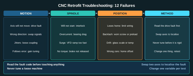
With the drive choice, the encoder strategy and the fault-finding procedure covered in the troubleshooting guide, and the pricing in the CNC retrofit cost calculator, this is the last of the four drive-train decisions in the parent retrofit guide.
Section summary. The selection is not finished until it is measured, and the measurement in ball screw vs lead screw vs rack and pinion is the one most people skip. A dial indicator and a spring scale, with the force recorded as well as the indicator reading, is what separates real backlash from structural deflection. The three things that ruin a ball screw – brinelling, contamination and overrunning in a vertical axis – are all preventable, and all three are common on Indian retrofits.
Related Reading
- CNC Machine Retrofit: Complete Guide
- Servo Motor Selection for CNC Retrofit
- Encoder Selection for CNC Axes
- Stepper vs Servo for CNC Retrofit
- CNC Retrofit Cost Calculator
Sources
- ISO 10360, Test conditions for geometric accuracy of numerically controlled machines
- ISO 230-2, Accuracy of self-contained numerically controlled turning machines
- THK Ball Screw Technical Handbook, Accuracy and Life Calculation
- LinuxCNC Documentation, Hardware Compatibility
Key Takeaways
- Thrust from torque is F = 2 pi eta T / lead, so a longer lead means more thrust per Nm of motor torque but more backlash and less resolution.
- Ball screw efficiency runs 85 to 95 percent, trapezoidal lead screw 30 to 50 percent, ACME 15 to 30 percent, so a lead screw wastes half the motor.
- Ball screw life is L = (C/Cp)^3 x 10^6 revolutions, and the cubic term means the load rating matters far more than the cycle count.
- A rack and pinion has no backlash and no screw to wear, but it needs a second support rail and a gearhead with a backlash-free output.
- Use a lead screw only where self-locking matters, such as a vertical axis without a brake, and only where the load is light.