Spindle Rebuild: Bearing Preload, Taper Condition and Runout Correction
Key Takeaway
A cnc spindle rebuild works by measuring runout before and after every stage, because each stage changes what the next measurement means. The runout at the nose tells you whether the spindle is the problem at all, the bearing preload determines whether it stays accurate under load, and the taper condition determines whether the runout you measure is the spindle’s or the chuck’s.
Spindle Rebuild: Preload, Taper and Runout
SYMPTOMS
Runout grows on the part
Noise changes with rpm
Heat at the front bearing
Taper has steps or rust
BEARING PRELOAD
Angular contact, matched set
Preload by feel or stretch
Too tight raises temperature
Too loose gives axial float
TAPER CONDITION
Inspect bore and shank
Clean and oil the taper
Check face flatness
Re-cut taper if stepped
RUNOUT
Dial indicator on spindle nose
Rotate by hand, 0.02 mm max
TIR not total indicator run
Repeat after the rebuild
Target spindle runout: under 0.02 mm
Check at the nose, not the flange
Angular contact bearings in matched sets
Preload raises heat when wrong
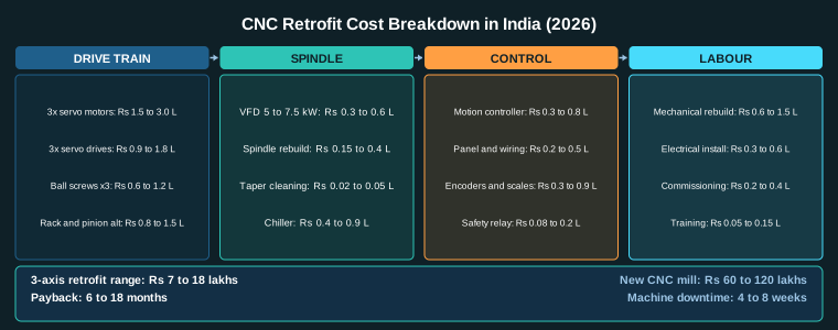
Figure 1: The spindle rebuild sequence, the symptom that points to each stage, and the check that closes it
Table of Contents
1. Why a Spindle Rebuild Is a Sequence of Measurements
A spindle rebuild is a sequence of measurements, not a replacement, and the sequence matters because each stage changes what the next measurement means. This guide takes it in order: runout at the nose, the register and the tool tip; then the bearing set and its preload; then the taper; then the runout again, and what can and cannot be corrected at the machine. The sections end with the acceptance test and the one-page record that makes the work worth doing.
A CNC spindle is a precision assembly of a shaft, a set of bearings, a taper, and a housing. Each of these can be the cause of the same symptom, and the symptom is nearly always the same: the finished part shows a variation that repeats with spindle rotation.
The rebuild is not a replacement. A replacement hides the diagnosis. A rebuild establishes where the error is, fixes it, and proves the fix by measurement. The sequence matters because each step changes the meaning of the next measurement.
| Stage | What you measure | What it tells you |
|---|---|---|
| 1. Baseline | Runout at the nose, the register and the tip | Whether the spindle is the source at all, and which component dominates |
| 2. Bearings | Noise, heat, axial float, preload | Whether the bearing set is the source, and what preload is required |
| 3. Taper | Condition of the bore and the shank | Whether the taper is transferring the error into the workpiece |
| 4. Verification | Runout again, plus a test cut | Whether the rebuild achieved what it was meant to achieve |
Section summary. The reason cnc spindle rebuild has to be a sequence is that a spindle has three separate error sources and each one masks the next. The nose reading tells you whether the spindle is the problem at all, the bearing preload decides whether it stays accurate under load, and the taper decides whether the runout you are measuring belongs to the spindle or to the chuck. Measure out of order and you will rebuild a spindle that did not need it.
A cnc spindle rebuild is worth doing for its own sake only when the baseline runout and the final runout are both recorded.
The dial indicator, the magnetic base and the test bar are a small investment, and they are what make a cnc spindle rebuild measurable rather than arguable.
2. Measuring Runout Properly
Runout measurement is the core skill, and most bad measurements come from using the wrong equipment or the wrong procedure.
The equipment
- Dial indicator with a deflection of 0.01 mm or less. A 0.02 mm indicator cannot resolve a 0.01 mm target and will give misleading results. The cost difference between a 0.01 mm indicator and a 0.02 mm one is a few thousand rupees.
- Magnetic base for mounting to the spindle housing, so the indicator does not sit on the machine’s moving parts.
- A test bar for the tip measurement: a precision-ground bar of known diameter, held in the chuck, so the indicator can read at a defined radius.
Never measure runout with a marker, a chalk mark, a steel rule or a laser. These give a number without a resolution, and they give it at a different point on the spindle than the one that matters.
Where to measure
| Measurement point | What it includes | Target |
|---|---|---|
| Spindle nose face | Face runout, which moves the tool axially | Under 0.01 mm |
| Chuck register / taper bore | Radial runout of the spindle nose | Under 0.01 mm |
| Tool tip in the chuck, on a test bar | Everything: spindle nose, taper, chuck, bar | Under 0.02 mm |
The procedure
- Mount the indicator on the spindle housing with the magnetic base. Never mount it on the table or on the quill, because then the measurement includes the structure’s own movement.
- Set the indicator to zero at the indicator’s mid-scale, so the runout is read in both directions without running out of travel.
- Rotate the spindle by hand, slowly, through at least two full revolutions. Do not use the spindle’s own motor for this measurement: at speed, the runout reading mixes in the dynamic behaviour and the balance, and the point of maximum runout is lost in the noise.
- Record the maximum deviation from zero and the minimum, and take the total indicator reading as the difference between them.
- Turn the chuck through one revolution in its clamped position and repeat. A change in the reading means the chuck is not running true on the taper.
Total indicator reading versus indicated runout
These are used loosely and they mean different things. Total indicator reading (TIR) is the maximum difference between the highest and lowest reading over a full rotation: it is the total swing and it is what the operator sees on the part. Indicated runout is the distance from the mean position to the extreme, which is half the TIR for a pure sinusoidal error. A spindle with 0.02 mm TIR has 0.01 mm indicated runout.
Specify TIR in the machine’s acceptance record, because it is the number that maps to the part.
The numbers that matter
| Machine class | Acceptable spindle nose TIR | Acceptable tip TIR on a test bar |
|---|---|---|
| General purpose job shop | 0.02 mm | 0.04 mm |
| Precision machining | 0.01 mm | 0.02 mm |
| High precision, grinding | 0.005 mm | 0.01 mm |
For context, a spindle that is out of tolerance produces a workpiece error of the same order as the runout, scaled by the ratio of the workpiece radius to the measurement radius. A 0.03 mm runout read at a 40 mm radius produces about 0.03 mm of variation on the diameter of a part cut at that radius.
Section summary. Most bad runout measurements come from the wrong equipment or the wrong procedure rather than from a bad spindle. A 0.01 mm deflection indicator, a magnetic base on the housing, and two hand-rotated revolutions are the minimum for cnc spindle rebuild to produce a number you can act on. And total indicator reading is not indicated runout: TIR is the total swing the part sees, and specified TIR is the number that belongs in the acceptance record.
The bearing set and the preload method are the parts of a cnc spindle rebuild where buying from a specialist pays for itself.
The taper is inspected before the bearings are ordered, because a damaged taper bore changes the rebuild plan and the parts list.
3. Bearings and Preload
Spindle bearings are almost always angular contact ball bearings, arranged in a set. The set is preloaded so that the bearing is always in contact under load in both directions, and that preload is the single most important setting in the whole spindle.
Why preload exists
Without preload, a spindle bearing carries its load through a point contact, and the shaft deflects under load, so the spindle does not return to the same position when the load is removed. The spindle is then non-repeatable. Preload removes that by keeping the rolling elements in continuous contact, which stiffens the bearing and makes the shaft behave as if it were supported on a continuous surface.
So preload trades two things against each other:
- Too little preload: the spindle is compliant, it has axial float, the bearing is not stiff enough to resist the cutting load, and the runout changes under load. The symptom is a part that is accurate when cut free and out of tolerance when cut under load.
- Too much preload: the bearing runs hot, the grease degrades faster, the balls skid rather than roll at low speed, and the failure comes early. The symptom is a spindle that is warm after a short run and whose noise increases with temperature.
The preload methods
Fixed preload. The manufacturer specifies a preload force or a preload value for the bearing set, and it is set by measuring the drag torque or the axial force required to move the shaft. The procedure:
- Fit the bearings with the manufacturer’s specified fit and shims, and set the preload with the spindle at a known temperature, usually around 20 to 25 degC.
- Measure the torque needed to rotate the shaft by hand, with a torque wrench or a spring scale on a lever arm, and compare with the manufacturer’s figure.
- The most common practical method is the axial displacement method: fit the bearing to a reference shaft with a known preload, measure the axial deflection under a specified axial load, and use that as the target for the spindle assembly.
Spring preload. A spring pushes the bearings together continuously. The spring’s force sets the preload and it does not change much with temperature, which is why springs are used on lathes and on high-speed spindles where the thermal growth is large.
Constant pressure. A hydraulic or pneumatic system holds a constant force on the bearings. This is the most accurate arrangement and it is used on high-precision spindles, because it cancels the thermal growth of the spindle. It is also the most expensive and the most maintenance-intensive.
The numbers
- Typical preload for a general CNC spindle: 0.5 to 1.5 times the radial load the spindle sees in normal cutting, or the manufacturer’s specified value, whichever is used.
- Axial stiffness. A properly preloaded spindle assembly has an axial stiffness of roughly 50 to 150 N per micron, or 50,000 to 150,000 N per mm. A spindle at the low end will deflect 0.01 mm under a 500 N axial load; at the high end it deflects 0.003 mm.
- Temperature rise. A correctly preloaded spindle running at its rated power should show a nose temperature rise of 15 to 30 degC above ambient after 30 minutes. Above 40 degC rise, the preload is too high or the bearings are damaged.
Installation mistakes that destroy a new bearing set
- Installing the bearings with power through the rolling elements. A bearing must be pressed onto the shaft or into the housing, never driven through the race that carries the load. On an angular contact set, this means the load during mounting must go through the correct shoulder, or the set is damaged before the spindle is ever run.
- Mixing bearings from different sets or different production batches. Use a matched set from one box, and keep the set together until assembly.
- Reversing the orientation of a single bearing in the set. The bearings in a matched set are marked for direction. The large shoulder goes one way. Get it wrong and the preload is not the specified preload.
- Not cleaning the housing bore and the shaft journal. The single most common cause of a bearing that fails a week after a rebuild is contamination left in the housing bore. The bore has to be cleaned and the same oil used to lubricate the bearing has to be used to clean it.
- Skipping the spindle run-in. A new bearing set needs a running-in period at a reduced speed and load before it goes to production.
The run-in procedure
- Run the spindle with no load at 25 percent of rated speed for 15 minutes.
- Increase to 50 percent for 15 minutes, then to 75 percent for 15 minutes.
- Then run it at rated speed under a moderate cutting load for 30 minutes.
- Re-measure the runout. A bearing set that has run in may have settled and the reading may have changed by a few microns. Record the new value as the acceptance value.
Section summary. The bearing preload is the single most important setting in cnc spindle rebuild, because it is what makes the spindle stiff enough to return to the same position when the load is removed. Too little preload and the part is accurate free but out of tolerance under load; too much and the bearing runs hot and the failure comes early. The installation mistakes here are the ones that destroy a new bearing set before the spindle is ever run.
The decision of what to correct at the machine and what to correct on the bench is the decision that sets the cost of a cnc spindle rebuild.
The acceptance test is the part of a cnc spindle rebuild that the customer, the auditor or the next technician will actually look at.
4. The Taper
The taper is the interface between the spindle and the tool, and it is where a great deal of runout enters a machine without the spindle itself being at fault.
What goes wrong
- Rust. A spindle that has been idle with the chuck off will have moisture on the taper. Rust on the taper shank transfers to the chuck bore, and then the chuck runs out.
- Steps. A worn bearing leaves a step on the taper face, typically at the position where the rolling element has been sitting. A step of even 0.01 mm is enough to produce 0.01 mm of runout.
- Damage from a stuck tool or a foreign object. A chip of hard steel embedded in the chuck bore scores the taper.
- Dust and swarf trapped between the taper faces. A single aluminium chip between the taper and the chuck is enough to produce 0.05 mm of runout. This happens on every machine and is the most common cause of “the runout appears suddenly”.
- Galvanic corrosion or a loose fit. A worn chuck that no longer grips the taper properly will slip.
The inspection procedure
- Remove the chuck and inspect the spindle taper bore with a good bore gauge or, if the spindle is large, with a small internal indicator on a mandrel.
- Inspect the shank with a magnifying glass or a bore scope. Look for the three classic defects: rust, a step on the face, and embedded debris.
- Check the taper fit with a dial test indicator on the chuck’s register face. A spindle taper is not a plain taper; it is a taper with a drive tang and a clearance. The chuck must seat fully on the taper and the register, and it must not rock.
- Clean properly. Use a taper cleaner, which is a wooden or plastic cone with a slot and a handle, loaded with the correct oil. Never use a file, never use emery cloth on the taper, and never use a wire brush. A file on the taper removes material and changes the fit permanently.
- Lubricate and fit. A thin film of spindle oil or molybdenum disulphide paste on the taper surfaces. Fit the chuck and rotate it by hand. It should seat with a light drag and should not rock.
The taper types
| Type | Taper | Typical use |
|---|---|---|
| BT | 7:24 | General job shop work. The workholding shoulder carries the thrust, so the spindle bearings see less axial load. |
| CAT | 1:20 | Higher torque and better seating. More common on lathes and on heavier work. |
| ISO / DIN | 1:20 or 7:24 | Heavy machining, large workholding. |
| HSK | Not a taper | Short, stiff, with a face contact. Common on high-speed machining centres. Not retrofit-friendly because the toolholder is expensive and non-standard. |
Section summary. The taper is where a great deal of runout enters a machine without the spindle being at fault, and the commonest cause in cnc spindle rebuild is a single aluminium chip between the taper and the chuck, worth 0.05 mm of runout by itself. The inspection procedure matters: a taper cleaner and the correct oil, never a file and never emery cloth, because filing the taper changes the fit permanently and cannot be undone.
A cnc spindle rebuild on a machine that will run unattended overnight needs the run-in period built into the commissioning plan, not added later.
A cnc spindle rebuild that is done on a lathe should also record the tailstock alignment, because it is disturbed whenever the chuck is changed.
5. Correcting Runout: What You Can and Cannot Fix
Once you have measured the runout, some causes can be corrected at the machine and some cannot. Knowing which is which saves a rebuild.
Correctable at the machine
- Contamination between the taper faces. Clean it and re-measure. This fixes a large fraction of “sudden” runout.
- The chuck, not the spindle. If the nose runout is fine but the tip runout is bad, the chuck is the problem. Remove it, clean the bore, and check the chuck for a stuck taper tang. A damaged tang in the spindle bore is a real possibility and it needs the spindle to come apart.
- An unbalanced holder. A tool holder that is not seated square, or a nut that is not torqued consistently, produces runout. Torque the nut properly and check the holder’s face.
- Axial float in the spindle. If the nose runout is small but the tool moves axially under cutting load, the bearing preload is too low. That is a rebuild, not an adjustment, unless the spindle has an adjustable preload mechanism.
Not correctable at the machine
- A bent spindle shaft. Only by replacing the shaft.
- A damaged bearing race or brinelled balls. Only by rebuilding the spindle.
- A scored taper bore or a damaged tang. Only by replacing or re-boring the spindle nose.
- A housing bore that is out of round or tapered. Only by replacing the housing. Check the bore with a bore gauge before accepting the new bearing set, because a new bearing in a damaged housing will fail again.
Measuring axial float
Push the spindle nose up and down with a dial indicator against the spindle face, and read the movement. This is the axial play of the spindle assembly.
- Under 0.005 mm: good.
- 0.005 to 0.01 mm: acceptable for general work, marginal for precision work.
- Above 0.02 mm: the preload is too low or a bearing is damaged. Rebuild.
Measuring the spindle’s thermal behaviour
Run the spindle at rated speed for 30 minutes and measure the temperature at the nose, the front housing and the rear housing with a thermocouple or an IR thermometer on a consistent surface.
- Uniform rise of 15 to 30 degC: normal.
- Front housing much hotter than the rear: the front bearing set is the heat source. Check the preload and the grease. This is the most common thermal signature of an over-preloaded spindle.
- Large rise with the spindle at no load: the bearings are dragging, or the cooling fan or the coolant is not working.
Section summary. Separating the correctable from the not correctable is what saves the cost of cnc spindle rebuild. Contamination, a faulty chuck, an unseated holder and a low preload on an adjustable spindle can all be dealt with at the machine. A bent shaft, a brinelled race, a scored taper bore and an out-of-round housing bore cannot, and only the last of these can be caught before the new bearing set is fitted, by checking the bore with a bore gauge.
The preload specification in a cnc spindle rebuild comes from the bearing manufacturer, and a preload guessed by feel is not a preload specification.
The one page record of a cnc spindle rebuild is what turns the next spindle fault from a day of investigation into a ten minute check.
6. The Acceptance Test and the Record
The rebuild is not finished when the spindle runs. It is finished when the result is measured and written down.
The test sequence
- Record the final nose runout with the indicator, in the same way as the baseline.
- Record the axial float.
- Record the tip runout on a known test bar, with the bar’s diameter noted.
- Make a test cut in the actual material: a stepped shaft or a set of diameters, measured with a micrometer at five positions. The spread across the readings is the machine’s practical radial runout at that diameter.
- Check the surface finish with a roughness comparator or a Ra measurement. Compare it with the same cut made before the rebuild.
- Record the temperatures after 30 minutes at rated speed.
- Repeat the runout measurement after the run-in period, and record the settled value.
The record that should exist
One page per spindle rebuild, in the machine’s documentation folder:
- Date, and who did the work
- Spindle make, model and serial number
- Bearing part numbers and the preload specification
- Baseline runout at the nose, the register and the tip
- Final runout at the same three points
- Axial float before and after
- Temperature rise at the nose and the housings
- Grease type and quantity, and the next lubrication interval
- The test cut results
That one page is what allows the next person to distinguish a spindle fault from a tool fault in ten minutes instead of a day, and it is what makes the difference between a machine that is maintained and a machine that is repaired. The VFD and parameter side of the spindle is in the spindle VFD guide, the lathe-specific procedure is in the CNC lathe retrofit guide, and the pricing of the spindle package is in the CNC retrofit cost calculator.
Section summary. The rebuild is not finished when the spindle runs, it is finished when the result is measured and written down. The acceptance sequence in cnc spindle rebuild covers final runout at the three points, axial float, tip runout on a known bar, a test cut in the real material, surface finish, temperature rise and the post-run-in value. One page of that record is what lets the next person separate a spindle fault from a tool fault in ten minutes.
In cnc spindle rebuild, the temperature rise tells you more about the bearings than the noise does, and it is the number most often left unrecorded.
The cost of a cnc spindle rebuild is dominated by the bearing set and the labour, and both of them are set by the machine class and the taper size.
Related Reading
- CNC Machine Retrofit: Complete Guide
- Spindle VFD Selection and Tuning
- CNC Lathe Retrofit Guide
- CNC Retrofit Troubleshooting
- CNC Retrofit Cost Calculator
Sources
- ISO 230-2, Accuracy of self-contained numerically controlled turning machines
- ISO 10360, Test conditions for geometric accuracy of numerically controlled machines
- SKF, Rolling Bearings Catalogue and the Basic Bearing Selection Process
- IMTMA, CNC Retrofit Guidance for Indian MSME Toolrooms
Key Takeaways
- Measure runout at the nose, at the chuck register and at the tool tip; three different numbers, and only the nose number belongs to the spindle.
- Use a dial indicator with a deflection of 0.01 mm or less and never measure runout with a marker or a chalk mark.
- Angular contact bearings must be installed in a matched set with the correct orientation, and the preload is set by the manufacturer method, not by feel.
- Clean the taper with a proper taper cleaner and never run a chuck on a dry or rusty taper, because that damages the new bearings.
- If the runout is correct but the parts still show chatter, the spindle is not the fault: look at the tool, the workpiece and the machine’s structural resonance.