Servo Motor Selection for CNC Retrofit: Torque, Inertia and Frame Size
Key Takeaway
Servo motor selection for a CNC retrofit is a chain of four calculations: convert the cutting force into screw torque, convert torque into motor torque through the screw efficiency, check the inertia ratio the drive has to accelerate, and confirm the speed the motor can hold at that torque. A motor that passes all four is the right motor, and a motor that fails any one of them is the wrong motor regardless of what the catalogue says.
Servo Motor Selection for CNC Retrofit
1. TORQUE
T = F x r at the screw
Add 30 pct margin
Check peak, not only rated
Frame below NEMA 23 often fails
2. POWER
P = 2 pi N T / 60
Convert to kW at 1500 rpm
Size drive for 1.5x power
Check regen and DC bus
3. INERTIA
Jload from screw and table
Ratio = Jload / Jmotor
Keep ratio under 10:1
Above 30:1 needs gearbox
4. SPEED
v = rpm x lead / 60
Check motor max rpm
4000 rpm is common limit
Verify gearbox ratio
Torque: T = F x r
Power: P = 2 pi N T / 60
Inertia ratio target: under 10:1
Add 30 pct torque margin
Figure 1: The four-step servo selection sequence and the formula behind each step
Table of Contents
1. The Four Numbers That Decide the Motor
The motor is the part of a retrofit that cannot be changed cheaply later, so it is the part to get right. This guide works through the four numbers that decide it – thrust, torque, inertia and speed – with the arithmetic shown at every step, because in servo motor selection for cnc retrofit the catalog does not choose for you. The sections end with a complete worked selection and a clear statement of when to stop calculating and use judgement.
Servo motor selection for a CNC retrofit is not a catalogue exercise. It is four numbers, in order:
- Thrust at the screw, from the cutting force the axis has to resist.
- Torque at the motor, after the screw efficiency and a margin.
- Inertia ratio, which decides whether the servo loop can actually control the axis.
- Speed the motor has to hold at that torque.
Get those four right and the frame size, the drive rating and the cost all follow. Get any one of them wrong and the machine will be either oversized, undersized, or limited by something the catalogue does not tell you.
Collect the input data first
Before any calculation, write down these six numbers for each axis. If you cannot get one of them, stop and go and get it, because every one of them changes the answer:
- Maximum cutting force on the axis, in newtons. This is not the same as the maximum force the slide can take; it is the force the work generates.
- The screw lead, in mm per revolution.
- The screw efficiency. A ball screw runs at 0.85 to 0.95; a trapezoidal lead screw runs at 0.30 to 0.50; a ACME screw at 0.15 to 0.30. Use the manufacturer value for the specific screw, not a generic figure.
- The axis mass being moved: the table or saddle, plus the cross slide, plus the workpiece, plus the fixture, plus the tool holder.
- The maximum feed rate required for the work.
- Any ratio in the drive: a belt reduction, a gearbox, or a servo with an integrated gearhead.
Section summary. servo motor selection for cnc retrofit comes down to four numbers, and every one of them is computed rather than chosen: the thrust at the screw, the motor torque after efficiency and margin, the inertia ratio the loop has to control, and the speed the motor must hold at that torque. Get all four and the frame size, the drive rating and the cost follow by themselves. Get one wrong and the axis is either oversized, undersized or limited by something the datasheet does not mention.
The budget for servo motor selection for cnc retrofit follows from the frame size, and the frame size follows from the torque, and the torque follows from the cut.
2. Step 1: Thrust and Torque
Step 1a: the force
The cutting force on a feed axis depends on the workpiece material, the tool and the cutting parameters. A usable engineering estimate for milling is:
F = specific cutting force x chip cross-section x feed per tooth correction.
Specific cutting force for mild steel with a carbide tool at normal speeds is roughly 1400 to 2000 N/mm^2, and for aluminium it is around 700 to 900 N/mm^2. Take a cut with a 6 mm cutter, 2 mm depth of cut and 0.1 mm per tooth feed. The chip cross-section is 6 x 2 = 12 mm^2. For mild steel at 1500 N/mm^2, F = 1500 x 12 = 18,000 N. That is a large force, and it tells you immediately that a light NEMA 23 servo on a machine that can take that cut is the wrong answer.
Step 1b: thrust at the screw
For a rotating screw drive, the relationship between thrust and torque is:
F = 2 pi eta T / lead, so T_screw = F x lead / (2 pi eta)
Using the example above: F = 18,000 N, lead = 10 mm = 0.010 m, eta = 0.90.
T_screw = 18000 x 0.010 / (2 x 3.1416 x 0.90) = 180 / 5.6549 = 31.8 Nm.
That is the torque the screw has to supply at the shaft. Note how the lead appears: halving the lead to 5 mm halves the torque needed, and doubling it to 20 mm doubles it.
Step 1c: the effective radius shortcut
The same calculation in its shortcut form uses the effective radius r = lead / (2 pi), so T = F x r:
For a 10 mm lead, r = 0.010 / 6.2832 = 0.001592 m. T = 18,000 x 0.001592 = 28.7 Nm.
The shortcut gives a slightly lower number than the full formula because it omits the efficiency term. Use it as a quick check and the full formula for the actual selection: 28.7 Nm from the shortcut versus 31.8 Nm with efficiency applied. The shortcut is a sanity check on the order of magnitude, not the design value.
Step 1d: margin and gearbox
Now add the margin. The margin has to cover three things: acceleration (which adds an inertial torque on top of the cutting torque), the fact that the quoted screw efficiency is a laboratory figure and a worn or dirty screw is worse, and the fact that the machine will see a harder cut than you planned for. Apply 1.3 as a reasonable working margin for a retrofit on a machine that will do general job work:
T_motor = 31.8 x 1.3 = 41.4 Nm at the motor shaft (before any gearbox).
If the drive has a gearhead with a ratio of 10:1, the motor only needs 4.14 Nm and the gearbox carries the load instead of the motor. This is the single biggest lever in servo motor selection for a CNC retrofit, and it is why a gearhead servo is often the right answer on a heavy axis.
Step 1e: check the screw and bearing ratings
A common error is to size the motor for the load and then fit a screw that cannot carry it. Check the dynamic load rating C of the ball screw against the actual axial load, and the thrust rating of the screw nut bearings. For the example: an 2508 ball screw has a dynamic load rating around 22 kN. An 18 kN working load is 82 percent of the rating, which is far too high for a continuous duty cycle. Either use a larger screw (2510 or 3208) or reduce the cutting force.
The life calculation then follows the standard form:
L = (C / Fm)^3 x 10^6 revolutions, where C is the dynamic load rating of the screw and Fm is the mean load, Fm = Fmin + (Fmax – Fmin) x 0.5 x 0.6 for a unidirectional load. The cubic term means the load rating dominates the life, not the number of revolutions.
Section summary. The first step in servo motor selection for cnc retrofit is to convert the cutting force into screw torque, and the only shortcuts worth knowing are the thrust relation F = 2 pi eta T / lead and the effective radius form T = F x r. The margin on top has to cover acceleration, a worn screw and a harder cut than planned. A gearbox is the single biggest lever in the whole selection, and it is often the right answer on a heavy axis.
A servo motor selection for cnc retrofit that starts from the motor catalogue rather than from the cutting force will oversize the axis and then under-size the drive.
3. Step 2: Power
The formula
Mechanical power from torque and speed:
P = 2 pi N T / 60, with N in rpm and T in Nm, giving watts.
Worked example
Continue with the Y axis: T = 31.8 Nm at the screw, maximum screw speed 600 rpm.
P = 2 x 3.1416 x 600 x 31.8 / 60 = 1999 W, call it 2.0 kW at the screw. With 90 percent screw efficiency and 95 percent motor and drive efficiency, the electrical input is 2000 / (0.90 x 0.95) = 2340 W, so about 2.4 kVA at the drive, or 3.2 kVA three phase at 415 V.
Why power is not the deciding number
Look at that 2.4 kVA against a typical 1.5 kW servo motor, which has a rated continuous output around 1.5 kW and a peak output near 3 kW. The peak covers the 2.0 kW mechanical demand, and the motor is only asked to deliver it for the duration of the cut, not continuously. So the motor fits, but only just, and only on peak.
Here is the important lesson: on a retrofit, the motor is sized by torque and by inertia, and the power number is a consequence. A motor with enough torque and enough power margin but too much rotor inertia for the load will still fail, because the controller will not be able to accelerate it fast enough. That is the subject of the next step.
RMS versus peak torque
Servo torque ratings are quoted in three ways and they are not interchangeable:
- Rated (continuous) torque is the torque the motor can hold indefinitely at 25 degC ambient with the stated cooling. This is the thermal limit.
- Peak (maximum) torque is the torque the motor can hold for a short period, typically 3 seconds. The ratio of peak to rated is usually 2.5:1 to 3:1.
- Repetitive peak is the torque that can be held repeatedly at a duty cycle the drive permits.
An Indian shop in summer, with the motor mounted on a cast iron bed inside a cabinet, will see an ambient above 40 degC. The derating is significant: the rated torque of a servo falls roughly in proportion to the temperature rise above the reference. Plan on the motor derating by at least 20 percent for a cabinet-mounted motor in an Indian summer, and size against that derated value.
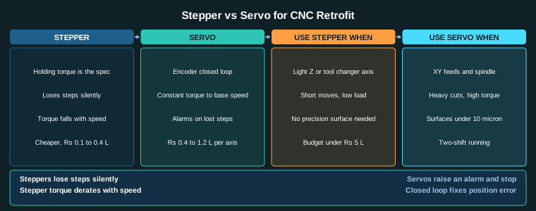
The stepper equivalent is worse still, because a stepper’s holding torque is quoted at standstill and the torque falls with speed and with current. The comparison is in the stepper versus servo guide.
Section summary. Power is the number people quote and the number that should not decide. P = 2 pi N T / 60 gives the mechanical output, but a retrofit motor is sized by torque and by inertia, and a motor can have ample continuous power and still fail to accelerate a heavy table quickly enough. This is also where the 40 to 45 degC ambient of an Indian summer has to be priced into the derating, because the rated torque is quoted at 25 degC.
The motor in servo motor selection for cnc retrofit also has to fit the machine physically, with a shaft that matches the coupling and the screw.
4. Step 3: The Inertia Ratio
This is the calculation most often skipped, and it is the one that explains a machine that cuts fine at low feed and then reports following errors at rapid traverse.
The ratio
Inertia ratio = J_load / J_motor, where J_load is the total inertia reflected to the motor shaft.
Calculating J_load
Three contributions, all referred to the motor shaft:
- The moving mass. J = m x r^2 for a mass m moving at a radius r from the motor axis. For a translating mass on a screw, the equivalent rotary inertia at the screw is J = m x (lead / 2 pi)^2.
- The screw’s own inertia. Usually small, but include it for a long screw.
- The motor rotor inertia. This is the denominator.
Worked example
Y axis: saddle mass 260 kg plus cross slide 90 kg plus fixture 60 kg, so m = 410 kg. Lead 10 mm, so the equivalent radius is 0.001592 m. J_screw = 410 x (0.001592)^2 = 410 x 2.534e-6 = 1.039e-3 kg m^2. The screw itself contributes about 0.15e-3, giving 1.19e-3 kg m^2 at the screw.
With a 1:1 belt or direct coupling, J_load at the motor = 1.19e-3 kg m^2.
A 1.5 kW 2000 rpm servo has a rotor inertia of 0.00085 kg m^2. Ratio = 1.19e-3 / 0.00085 = 14.0.
With a 2.0 kW motor at 0.00135 kg m^2, ratio = 8.8. With a 3.0 kW motor at 0.0025 kg m^2, ratio = 4.8.
Reading the number
| Ratio | What it means | What to do |
|---|---|---|
| Below 5:1 | Very easy to control | Excellent. Maximum acceleration available. |
| 5:1 to 10:1 | The comfortable design range | Target this. Tunable with standard gain settings. |
| 10:1 to 30:1 | Marginal | Needs careful tuning, lower acceleration, and a good drive. Do not expect full performance. |
| Above 30:1 | Poorly controllable | Fit a gearbox, or a motor with a much higher rotor inertia, or reduce the moving mass. |
The gearbox lever
A gearbox does two things: it multiplies the torque, and it multiplies the inertia ratio by the square of the ratio. A 10:1 gearbox with a 410 kg load gives a ratio of 14.0 x 100 = 1400:1 reflected to the motor, which sounds terrible, but the gearbox’s own ratio reduces the reflected inertia by the square of the ratio while the torque advantage reduces the required motor torque. The net effect is that the gearbox makes the axis easier to control, at the cost of backlash and of reduced stiffness. Choose a backlash-free or minimal-backlash gearhead for a CNC axis; a standard helical gearhead with 5 arcmin backlash will show up directly in the finished part.
Acceleration is what actually tests the ratio
The inertial torque during acceleration is T_accel = J x alpha. For the example with J = 1.19e-3 kg m^2, if you want the axis to reach 3000 mm/min (with a 10 mm lead, that is 300 rpm) in 0.1 second, then alpha = 300 rpm in 0.1 s = 300 x 2 pi / 60 / 0.1 = 314 rad/s^2, and T_accel = 1.19e-3 x 314 = 0.374 Nm at the motor. That is small against 41.4 Nm, so on this axis the acceleration is not the binding constraint, the cutting force is. But if you reduce the acceleration time to 0.05 s, the inertial torque doubles to 0.75 Nm, still small. Now check the same axis with a 10:1 gearbox: the motor has to make the same acceleration, so the inertial torque at the motor is J_motor_reduced x alpha, and the load inertia referred to the motor drops to 1.19e-3 / 100 = 1.19e-5 kg m^2, which is now far below the rotor inertia, so the ratio becomes 1.19e-5 / 0.00085 = 0.014, which is trivially controllable. This is exactly why gearboxes are used on heavy axes even when the motor could do it without one: it puts the axis in the band where the loop is stable and the tuning is easy.
Section summary. The inertia ratio is the calculation most often skipped and the one that explains a machine that cuts fine at low feed and then reports following errors at rapid traverse. Under 10:1 is comfortable, above 30:1 needs a gearbox, and a gearbox improves controllability by reducing the reflected inertia by the square of its ratio. The servo motor selection for cnc retrofit answer is only trustworthy once this number is on paper.
A servo motor selection for cnc retrofit that is done only to the torque step will produce a motor that cannot be accelerated, and that fault does not show up until the first rapid traverse.
5. Step 4: Speed, Frame Size and the Drive
Speed
Feed rate and screw speed are linked: v = N x lead / 60.
For a 3000 mm/min feed on a 10 mm lead, N = 3000 x 60 / 10 = 1800 rpm. For a 5000 mm/min feed, N = 3000 rpm. Most servo motors rated 2000 rpm run to 3000 rpm at reduced torque, and 4000 rpm if they are wound for it. Check the motor’s speed-torque curve, not just its maximum speed. Above base speed the torque falls, and the falling torque may fall below what the axis needs.
Frame size
| Frame | Square | Typical torque range | Where it fits |
|---|---|---|---|
| NEMA 17 | 42 mm | 0.1 to 0.4 Nm | Light Z axis, small router, feed only. Not a CNC feed axis under load. |
| NEMA 23 | 57 mm | 0.5 to 3.5 Nm | The practical floor for a CNC feed axis. Suitable up to about 800 N of cutting force with a 10 mm lead. |
| NEMA 34 | 86 mm | 3 to 14 Nm | Heavy XY axes, medium machines, direct-drive applications. |
| NEMA 42 / 43 | 107 / 110 mm | 12 to 48 Nm | Heavy machining, large ball screws, high thrust. |
The rule of thumb for a retrofit: NEMA 23 is the minimum for an XY feed axis. If your calculation lands on more than about 2.5 Nm continuous, go to NEMA 34 rather than trying to run a NEMA 23 at its limit.
Drive sizing
Size the drive for the motor’s peak current, not its rated power, and add margin for the DC bus. Rules that hold in practice:
- Drive rated current at least 1.2 times the motor’s rated current. Motors with high inductance and low resistance need a drive with a high voltage, not just a high current.
- Drive voltage must cover the motor’s back-EMF at maximum speed plus margin. Back-EMF is approximately V = Ke x N, with Ke typically 0.03 to 0.06 V per rpm for a 2000 rpm motor. For a motor at 3000 rpm with Ke = 0.04, that is 120 V, so a 200 V drive is needed, and a 220 V single phase supply is marginal for regen. This is why three phase 415 V drives are the norm for CNC servos.
- Check the regenerative capability. A servo decelerating a heavy axis returns energy to the DC bus. If the drive has no braking resistor and the machine stops often, add one. The resistor dissipation can be calculated from the regenerative power, which for a deceleration at constant power is roughly P_regen = F x v.
Cable sizing
Motor power cable current is the motor’s rated current plus the drive’s switching ripple. Use the manufacturer’s table rather than a rule of thumb, but know the failure mode: an undersized cable is a voltage drop problem first and a heat problem second. For a 4.5 A motor at 30 m, a 1.5 mm^2 conductor has a loop resistance of 2 x 30 x 0.0175 / 1.5 = 0.70 ohm, giving a drop of 4.5 x 0.70 = 3.15 V, which is 1.4 percent of 220 V. The drive’s fault detection can trip on this during acceleration.
Section summary. Speed, frame size and drive sizing are where the catalogue finally gets consulted, but by then the answer is already determined. NEMA 23 is the practical floor for a feed axis, the drive has to be rated for the motor’s peak current and for the back-EMF at top speed, and the cable has to be sized for voltage drop rather than for convenience. This is the last step in servo motor selection for cnc retrofit and it is mostly a matter of checking the arithmetic again.
The inertia ratio in servo motor selection for cnc retrofit is the number the drive engineer will ask for first, so have it written down before the purchase order goes out.
6. A Complete Worked Selection
Pulling it together for one axis, so the sequence is visible end to end.
Input
- Cutting force: 1200 N (light aluminium cut, 4 mm cutter, 1.5 mm depth)
- Screw lead: 10 mm, efficiency 0.90
- Moving mass: 180 kg total
- Max feed: 3000 mm/min
- Ratio: direct, 1:1
The numbers
| Quantity | Calculation | Result |
|---|---|---|
| Thrust at screw | Equal to the cutting force | 1200 N |
| Torque at screw | T = F x lead / (2 pi eta) = 1200 x 0.010 / 5.6549 | 2.12 Nm |
| Motor torque with 1.3 margin | 2.12 x 1.3 | 2.76 Nm |
| Screw speed at 3000 mm/min | N = v x 60 / lead = 3000 x 60 / 10 | 1800 rpm |
| Mechanical power | P = 2 pi N T / 60 = 2 x 3.1416 x 1800 x 2.12 / 60 | 400 W |
| Load inertia at motor | J = m (lead / 2 pi)^2 = 180 x (0.001592)^2 | 4.56e-4 kg m^2 |
| Inertia ratio with a 0.85e-3 motor | 4.56e-4 / 0.85e-3 | 0.54 : 1 |
The decision
Motor torque needed is 2.76 Nm at 1800 rpm continuous. A NEMA 23 servo rated 2.8 Nm continuous and 8.4 Nm peak at 2000 rpm fits with margin at 1800 rpm, and the inertia ratio of 0.54:1 is trivial, so the axis will be fast and easy to tune. A NEMA 17 rated 1.3 Nm continuous fails the torque requirement. The drive should be rated at 3.5 A minimum for a 3 A rated motor, and with a 200 V DC bus minimum.
Note the structure of the answer: torque selected the frame, speed confirmed it, and the inertia ratio confirmed that the machine will be controllable. Any one of the three alone would have produced a wrong answer.
When you should stop calculating
Three situations where the standard method does not apply and judgement should take over:
- Very short travel axes with a high load, such as a turret index or a tool changer. Here the gearbox, not the motor, is the design.
- Axes with a belt reduction. A 2:1 or 3:1 belt reduction changes the reflected inertia and the torque, and the belt’s elasticity introduces a resonance into the servo loop. Model it or use a direct coupling.
- Spindle axes, where the load is completely different from a feed axis. The spindle motor is sized by power and by the spindle’s own inertia, and the calculation method is entirely separate. That is covered in the spindle VFD guide.
And the final check before ordering anything: the selected motor must fit the machine physically, must have a shaft that matches the coupling and the screw, and the drive must be available with a serviceable supply in India. The CNC retrofit cost calculator then prices the decision, and the parent retrofit guide covers the mechanical side that the motor has to live with.
Section summary. The worked selection is the summary of servo motor selection for cnc retrofit: torque chose the frame, speed confirmed it, and the inertia ratio confirmed that the axis would be controllable, and any one of the three alone would have given a wrong answer. The three cases where the standard method does not apply – short travel axes, belt-reduced axes and the spindle – are worth knowing before you start, because they change the method rather than the numbers.
A servo motor selection for cnc retrofit also has to survive a 45 degC cabinet, and that derating is applied to the rated torque before any margin factor is added.
Related Reading
- CNC Machine Retrofit: Complete Guide
- Stepper vs Servo for CNC Retrofit
- Ball Screw vs Lead Screw vs Rack and Pinion
- Encoder Selection for CNC Axes
- LinuxCNC Hardware Configuration
- CNC Retrofit Cost Calculator
Sources
- ISO 230-2, Accuracy of self-contained numerically controlled turning machines
- ISO 10360, Test conditions for geometric accuracy of numerically controlled machines
- LinuxCNC Documentation, Hardware Compatibility
- Mesa Electronics, 5i/7i Series Motion Hardware
Key Takeaways
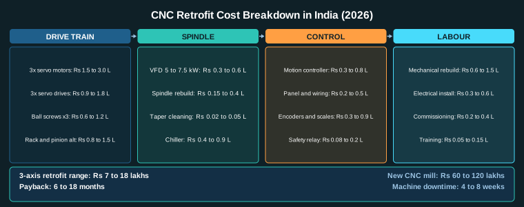
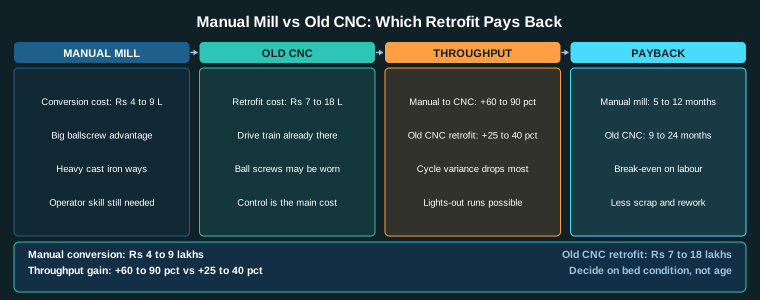
- Convert the axis load into screw torque first with T = F x r, then divide by the screw efficiency and multiply by a margin of 1.2 to 1.5.
- Power follows from P = 2 pi N T / 60, but on a retrofit the motor is sized by torque and inertia, not by continuous power.
- Keep the inertia ratio Jload/Jmotor under 10:1; above 30:1 the axis needs a gearbox, and no amount of controller tuning fixes it.
- The NEMA 23 frame (57 mm) is the practical floor for CNC feed axes; NEMA 17 is too small for anything with real cutting load.
- Size the drive for the motor’s peak current, not its rated power, and remember that a 30 percent duty cycle in the shop still has to accelerate the table every move.