Limit Switches, Homing and Proximity Sensors for CNC Machines
Key Takeaway
Limit switches and homing for cnc machines need three separate devices doing three separate jobs: a hard limit that removes drive power at the end of travel, a home switch that defines the machine zero, and a soft limit that the controller enforces in software. The most common machine fault in this area is a hard limit wired as a home switch, and the symptom is an axis that homes to the wrong end and crashes.
Limits, Homing and Proximity Sensors
HARD LIMITS
Mechanical switch, NC contact
Stops drive immediately
Not a position reference
Placed beyond soft limit
HOME SWITCH
Gives a repeatable origin
Inductive prox on flag
Back off, then slow approach
Second pass for repeatability
PROXIMITY
No mechanical contact
8 mm sensing range typical
Needs a metal target flag
Chatter and oil affect it
SOFT LIMITS
Set in the controller
Only valid after homing
Enforce in the software
Backup the values
Hard limit is not a home switch
Home switch gives the origin repeatably
Use a two-stage home move
Back off, then slow second approach
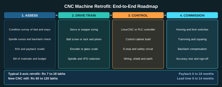
Figure 1: The three position-sensing devices on a CNC axis and the distinct job each one does
Table of Contents
1. Three Devices Doing Three Different Jobs
Three devices that keep getting confused: the hard limit that stops the drive, the home switch that defines zero, and the soft limit that the controller enforces. Mixing them up is why machines stop with an axis at the wrong end. This guide separates the three, gives the placement arithmetic for the hard limits, explains why a two-stage homing move is repeatable, and lists the wiring failures in the order of probability. The sections end with a monthly verification routine.
Most retrofit problems with limits and homing come from treating these as one subject. They are three separate functions, and each has a different requirement for speed, safety and reliability.
| Device | Function | Must work when | Typical technology |
|---|---|---|---|
| Hard limit switch | Removes drive enable at the end of travel | Always, even if the software is wrong or the operator has overridden it | Normally closed mechanical roller or a solid-state limit switch |
| Home switch | Defines the machine zero for one axis | At every power-up and after any fault | Inductive proximity sensor on a steel flag |
| Soft limit | Refuses a commanded move outside the working range | Only while the position feedback is valid | Software, in the controller |
Why the separation matters
A hard limit is a safety function. It has to work when everything else has failed: when the control software is corrupted, when the soft limit has been mis-entered, when the position feedback has lost count, when an operator has typed a wrong coordinate. It does this by being wired so that its action is a physical removal of the drive enable, not a message to the software.
A home switch is a reference function. It is not a safety function, and it does not need to be, but it does need to be repeatable, because every job the machine does starts from the position it establishes.
A soft limit is a convenience and a mistake-catcher. It is the first line of defence and the least reliable of the three.
Section summary. The confusion in limit switches and homing for cnc is expensive because the three devices have completely different failure requirements. A hard limit is a safety function that has to work when the software is wrong, so it acts by physically removing the drive enable. A home switch is a reference function that has to be repeatable. A soft limit is a convenience and the least reliable of the three, and it is the one most often mistaken for protection.
The three devices cost very little, and in limit switches and homing for cnc the total is a few thousand rupees against the cost of a crashed axis.
2. Hard Limits
How they work
A hard limit is wired into the drive’s enable chain or into the safety relay, so that when it opens, the drive is de-energised and the axis stops. There are two common architectures:
- Series in the drive enable. The limit switch is in series with the drive’s servo enable line. When it opens, the drive drops the motor torque. This is simple and works, but it depends on the drive’s enable being a safe output, which on older drives it is not.
- Into the safety relay, which removes the drive enable. The limit switch is a safety input to the safety relay, which then removes the servo enable and the contactor power. This is the architecture that satisfies a safety requirement, and it is the one to use on a retrofit where the E-stop is also a monitored safety function under ISO 13849-1.
Electrical design
- Normally closed contacts. A normally closed contact fails safe: if the wire breaks or the contact welds, the circuit opens and the machine stops. A normally open contact fails dangerously: a broken wire looks identical to “not triggered”.
- Positive opening. The switch must be a positive-opening device, meaning that the contacts cannot stay closed if the actuator fails. This is required for the E-stop and it is good practice for the limits. IEC 60204-1 is the reference for the general requirements of machine electrical equipment.
- Separate switch per end per axis. Three axes means six limit inputs. Do not share a common wire between the negative and positive limit of the same axis, because then a wiring error can short out both switches.
- Test the limit, do not trust it. After installation, verify each limit by jogging the axis into it slowly and confirming that the drive drops enable. Verify it again after any rewiring.
Where to place them
Place the hard limits beyond the maximum useful travel of the axis, but not so far beyond that the axis can travel into a mechanical stop and damage the drive train before the switch is reached.
The travel to leave depends on the stopping distance. At 3000 mm/min, which is 50 mm/s, with an acceleration of 200 mm/s^2, the stopping distance is v^2 / (2a) = 2500 / 400 = 6.25 mm. Add a margin of 10 mm and the limit goes 16 to 20 mm beyond the maximum working travel. A machine whose limits are placed 200 mm beyond the travel is a machine where the axis will hit the mechanical stop before the limit is reached, and a mechanical stop on a servo-driven axis is an expensive event.
On a retrofit, put a physical bumper or a rubber buffer at the end of travel as a last-resort mechanical protection, and make sure the drive’s parameter limits are set inside the physical limit.
Section summary. The hard limit belongs in the drive’s enable chain or, better, into the safety relay that removes the drive enable, because that is the architecture that satisfies ISO 13849-1 alongside the E-stop. Normally closed contacts fail safe, and the switch must be positive-opening. The placement in limit switches and homing for cnc is arithmetic: at 3000 mm/min with 200 mm/s^2 the stopping distance is 6.25 mm, so the limit goes 16 to 20 mm beyond the working travel, not 200 mm.
A hard limit in limit switches and homing for cnc that is wired as a normally open contact is the single most dangerous piece of wiring on a machine.
3. The Home Switch
What the home switch has to do
The home switch provides a repeatable, unambiguous physical reference. Its requirements are different from a limit’s:
- Repeatability. The switch must trigger at the same point every time, to within a fraction of the position resolution.
- Unambiguity. It must be clear which end of the axis it refers to, and which direction the axis was travelling when it triggered.
- Speed independence. The reading must be the same whether the axis approached at 50 mm/min or at 3000 mm/min.
Inductive versus mechanical
| Property | Inductive proximity sensor | Mechanical limit switch |
|---|---|---|
| Contact wear | None | Yes, the main failure mode |
| Signal bounce | None | Yes, needs filtering |
| Repeatability | Under 0.01 mm | 0.05 to 0.2 mm, degrades with wear |
| Speed sensitivity | None, within the response time | Significant, because of the bounce and the actuation time |
| Contamination tolerance | Good, unless coated in swarf or oil | Poor, chips jam the lever |
| Cost | Rs 600 to Rs 2,000 | Rs 250 to Rs 900 |
| IP rating | IP67 typical | IP54 to IP67 |
| Typical sensing distance | 1 to 8 mm for an 8 mm sensor | Fixed mechanical travel |
On a retrofit, the inductive sensor wins clearly. The mechanical switch’s repeatability degrades exactly when the machine is busiest, and the failure is a slow drift in the home position rather than an obvious fault, which is the worst kind of failure to diagnose.
Sensor selection
- Sensing distance and target. An 8 mm shielded inductive sensor typically senses a 6 mm mild steel target at 4 mm. The sensor’s datasheet gives the correction factor for the target material and thickness: a stainless flag needs a larger sensor or a thicker flag. Use mild steel or a dedicated 6 mm flag.
- Output type. PNP normally open is standard for 24 V DC. PNP normally closed is better for a home switch, because a broken wire then reads as triggered.
- Response time. An inductive sensor’s response time is typically 0.1 to 1 ms. A mechanical switch’s actuation time can be 5 to 20 ms, and at 3000 mm/min a 20 ms delay is 1 mm of overshoot, which is why the approach speed matters.
- LED indicator on the sensor. Buy the ones with a built-in LED. It turns the “is this sensor detecting anything” question from a wiring exercise into a visual check, and it is worth more than the sensor costs.
The flag
The flag is a piece of mild steel attached to the moving part, positioned so the sensor sees it at the reference point. Practical rules:
- Fix the flag with screws, not with epoxy, so it can be repositioned. Glue will let go at exactly the wrong moment.
- Make the flag tall enough to cover the sensor’s full sensing distance plus the overshoot at the approach speed. At 3000 mm/min and a 20 ms sensor response, that is 1 mm of travel plus the sensor’s own hysteresis of typically 0.1 to 1 mm. A 5 to 8 mm tall flag is sensible.
- Make the flag wide enough that the sensor cannot miss it if the axis is slightly skewed. A 10 mm wide flag on an 8 mm sensor gives margin.
- Fix the sensor on a rigid bracket, aligned square to the flag, and lock the bracket. A sensor that has been nudged 2 mm out of alignment will trigger late and inconsistently.
Section summary. The home switch has a different job and different requirements: repeatability, unambiguity about which end it refers to, and speed independence. The inductive sensor wins on a retrofit because it has no contact wear and no bounce, and because the mechanical switch’s repeatability degrades exactly when the machine is busiest. The failure mode is a slow drift in the home position rather than an obvious fault, which is the hardest kind of fault to diagnose.
An inductive sensor costs a few hundred rupees more than a mechanical switch and is the better choice in limit switches and homing for cnc on almost every retrofit.
4. Designing the Homing Sequence
The two-stage move
This is the core technique and it is worth understanding rather than copying.
Stage 1: fast approach. Move toward the flag at a fast homing speed, for example 2000 mm/min, until the switch triggers.
Stage 2: back off. Move away from the flag by a fixed distance, for example 10 mm, at a moderate speed, until the switch releases.
Stage 3: slow approach. Move toward the flag again at a creep speed, for example 50 mm/min, until it triggers. This is the position that becomes the machine zero.
Why three stages and not one? Because the trigger point depends on the approach speed and on the sensor’s hysteresis. Approaching fast, the sensor triggers late by the overshoot distance plus the hysteresis. Approaching slowly, it triggers much closer to the true edge of the flag, and much more repeatably. The slow final approach makes the home position repeatable to within the sensor’s hysteresis, typically 0.1 to 1 mm for an inductive sensor, and with a flag position set once and left alone, that is stable enough to be a working reference.
The direction problem
The homing sequence has to know which direction to approach from, because the trigger point differs by direction. The standard solution is a consistent search direction for each axis. If the axis always homes in the same direction, then the home position is always approached the same way and the repeatability holds. If the machine can home from either direction, the home position will differ by the hysteresis between the two directions, which on an inductive sensor can be 0.5 mm or more.
The alternative is to use a two-flag arrangement or a short and a long flag, so the controller can determine the direction from the flag it hit. This is more work and is usually not worth it on a retrofit.
Immediate versus incremental homing
- Immediate homing sets the machine zero at the switch trigger point. Simple, and the home position moves if the flag is moved.
- Incremental homing backs off to a known mechanical position, for example the end of travel, and uses the distance travelled from the switch as an offset. More repeatable against flag drift, more complex, and rarely needed on a retrofit.
The homing order and the interlock
Home the axes in a defined order, and make sure the order is safe. On a mill, home Z first so the tool is clear, then X and Y. On a lathe, home the turret reference and Z before X.
More important: the axes must not be allowed to move during homing in a way that causes a collision. A common fault on a retrofit is that homing X causes the table to run into the column because the machine’s travel is physically asymmetric and the homing direction was chosen wrong. Test each axis’s homing direction manually with the drives in manual mode before enabling the automatic sequence.
Section summary. The two-stage, really three-stage, homing move in limit switches and homing for cnc is worth understanding rather than copying. Fast approach, back off by a fixed distance, then a slow creep approach, and it is the third stage that makes the home position repeatable because the trigger point depends on approach speed and on sensor hysteresis. A consistent search direction matters for the same reason, since the hysteresis between two directions can be 0.5 mm.
The repeatability of the home position in limit switches and homing for cnc is what every job on the machine inherits, so it is worth measuring rather than assuming.
5. Wiring and the Failure Modes
Signal wiring
- Shielded cable for the sensors, or at least a cable rated for the environment. The sensor signals are small and they sit next to the VFD output cable.
- Keep the sensor cable away from the motor and VFD output cables. Minimum 200 mm, and never parallel.
- Terminate with ferrules and label every wire. A home switch that intermittently fails because of a loose terminal is the most common cause of a homing fault.
- Do not run the sensor return through the same cable as the power. Use a separate return, or use the shield as the return in a properly designed single-ended input.
Input filtering
The digital input modules have an input filter time, and this is a setting that matters more than most people expect. A mechanical switch bouncing for 5 ms will produce several false transitions unless the filter is set longer than the bounce. Set the filter to 10 to 20 ms for mechanical switch inputs and to 1 to 2 ms for inductive sensors, which have a clean signal.
But a filter that is too long slows the machine’s reaction to a limit. A limit input with a 20 ms filter means the axis can travel a further 20 mm after the switch is hit at 3000 mm/min. That is why the hard limit should be on a fast input path where the drive itself handles it, rather than going through a filtered PLC input.
Diagnosing a machine that will not home
In probability order:
- The flag is not in the sensor’s range, or the sensor’s LED is off. Check the LED first, every time. This is the most common fault by a wide margin, and it costs nothing to check.
- The wiring is wrong or the terminal is loose. Check the input’s state in the controller’s I/O display while physically actuating the switch by hand. The display must change. If it does not, the fault is in the wiring or the sensor, not in the software.
- The input is inverted. If the switch is normally closed and the controller is configured for normally open, the axis will home the instant it starts, or will not home at all. Check the polarity against the physical state.
- The homing direction is wrong. The axis moves away from the switch instead of towards it, and the homing routine times out. Check by jogging in manual mode.
- The homing speed is too high. If the axis overshoots the flag at 3000 mm/min and the flag is only 8 mm tall, the switch may never trigger properly. Reduce the search speed.
- The flag is loose. It has moved, or a bolt has worked loose. The home position has drifted and nobody knows how far.
- The input filter is too long, and the machine is moving faster than the filter can respond at the moment of triggering. Rare, but it happens with a mis-scaled feed.
The same symptom-led method for other motion faults is in the CNC retrofit troubleshooting guide.
Section summary. The wiring of limit switches and homing for cnc is where the faults live, and the ranked list of reasons a machine will not home starts with the one that costs nothing to check: the sensor’s LED is off. Beyond that come the loose terminal, the inverted input, the wrong homing direction and the overshoot on a flag that is too short. The input filter time is a setting that matters more than most people expect, and it is a trade between bounce rejection and how far the axis travels after the limit is hit.
The input filter setting in limit switches and homing for cnc is a compromise between rejecting bounce and reacting quickly to a limit, and it has to be set deliberately.
6. Verifying and Maintaining the Setup
The verification routine
Run this at commissioning and then once a month, and keep the record with the machine’s documents.
- Home the machine three times from a cold start and record the position readout each time. The spread across the three readings is the repeatability of the homing system. It should be under 0.5 mm for an inductive sensor on a retrofit, and under 0.1 mm if the flag and sensor are well set up.
- Home from a different starting position each time, for example from the middle of travel and from the far end. If the home position changes with the starting position, the homing sequence is finding something other than the flag, or the flag is being missed and the routine is ending on a timeout.
- Test each hard limit by jogging into it slowly and confirming that the drive drops enable. Do this for all six limits on a three-axis machine.
- Check the soft limits against the physical travel and against the hard limits. The soft limit should be inside the hard limit, and the hard limit should be inside the mechanical stop.
- Mark the flag position with a paint mark on the moving part and a corresponding mark on the fixed part. After a year you will be able to see at a glance whether the flag has moved.
What to do after a collision
After any crash into a limit or a mechanical stop, do not simply reset and carry on. Check:
- The homing position. A crash can move the flag, or bend the sensor bracket, and the next homing will be wrong.
- The screw and the coupling for damage. A crash that lost a step will not show up as a fault.
- The sensor bracket for alignment, and retighten it.
- That the hard limit still functions, by testing it.
The safety side
The E-stop is the one device that must not depend on the software, and the limit switches are the devices that must act before the software does. In the safety architecture for the machine, the E-stop, the guard door and the hard limits all feed the safety relay, and the safety relay removes the drive enable and the contactor power. The safety function must meet the performance level required for the machine under ISO 13849-1, and for a retrofit the honest answer for most machines is a Category 3, PL d architecture with a monitored safety relay.
Two rules close this out. First, never route a hard limit through the normal PLC input and then rely on the software to stop the drive. That is a software function wearing a safety function’s clothes. Second, never let the soft limit be the only protection against a soft limit, because a soft limit does not protect against a wrong position count, and a wrong position count is exactly what a retrofit with a broken encoder cable produces.
For the electrical architecture these limits live in, see the LinuxCNC hardware configuration guide. For the mechanical side of the reference flag and the axis, see the parent retrofit guide and the CNC lathe retrofit guide.
Section summary. Verification is a monthly routine and a commissioning gate: home three times from a cold start and record the spread, home from different starting positions, test each hard limit by jogging into it, and check that the soft limit sits inside the hard limit and the hard limit inside the mechanical stop. Marking the flag so that a year of drift is visible at a glance is the cheapest safeguard in limit switches and homing for cnc, and after any collision the flag, the bracket and the limits all have to be rechecked.
The monthly verification routine for limit switches and homing for cnc takes twenty minutes and is the cheapest fault prevention available on the machine.
Related Reading
- CNC Machine Retrofit: Complete Guide
- CNC Retrofit Troubleshooting
- LinuxCNC Hardware Configuration
- Encoder Selection for CNC Axes
- CNC Lathe Retrofit Guide
- CNC Retrofit Cost Calculator
Sources
- IEC 60204-1, Safety of machinery and electrical equipment of machines
- ISO 13849-1, Safety of machinery and safety-related parts of control systems
- ISO 10360, Test conditions for geometric accuracy of numerically controlled machines
- LinuxCNC Documentation, Hardware Compatibility
Key Takeaways
- A hard limit removes drive enable; a home switch defines zero; a soft limit is enforced in software. They are three different functions.
- Use a two-stage home move: fast approach, back off, slow second approach. The second approach is what makes it repeatable.
- Inductive proximity sensors are better than mechanical switches on a retrofit: no contact wear, no bounce, no lubrication.
- Wire the home switch as normally closed so a broken wire reads as triggered rather than as open, and the machine fails safe.
- Never rely on a soft limit as protection. Software can be overridden, a limit can be mis-scaled, and a soft limit does nothing when the position feedback is wrong.