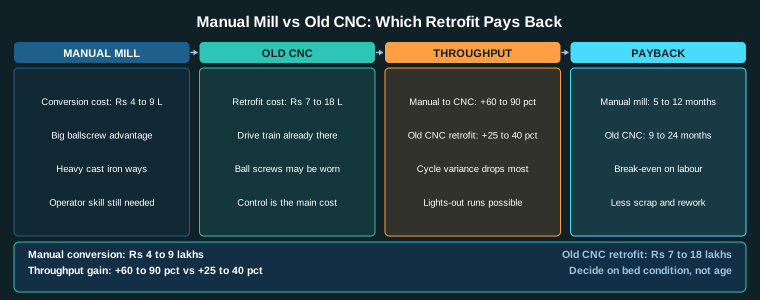
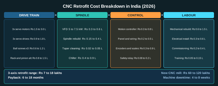
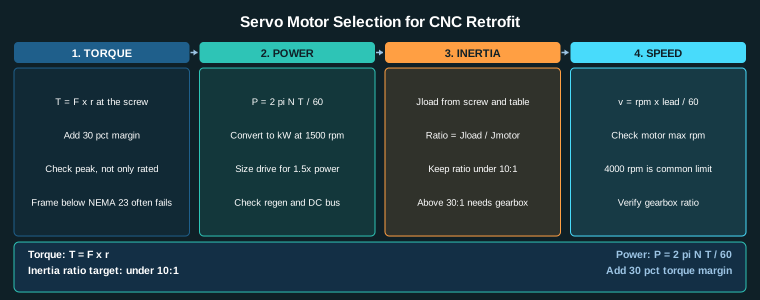
CNC Retrofit Troubleshooting: The 12 Failures That Stop a Machine
Key Takeaway
Cnc retrofit troubleshooting is a ranking exercise, not a guessing exercise: for each symptom the causes have an order of probability, and the test for each cause is cheap. Always read the drive fault code first, always change one thing at a time, and never start tuning a machine that is not mechanically rigid, because tuning a loose machine hides the real fault and makes the next fault worse.
CNC Retrofit Troubleshooting: 12 Failures
MOTION
Axis will not move: drive fault
Wrong direction: swap signals
Jitters: loose coupling
Follows error: gain tuning
SPINDLE
Will not start: interlock
Overcurrent: bearing drag
Surge: VFD ramp too fast
No torque: brake not released
POSITION
Loses home: limit wiring
Backlash: worn screw or preload
Drift: glass scale or temp
Wrong zero: home offset
METHOD
Read the drive fault first
Swap axes to localise
Never tune before it is rigid
Change one thing, retest
Read the fault code before touching anything
Swap two axes to localise the fault
Never tune a loose machine
Change one variable per test
Figure 1: The four fault families on a retrofitted CNC and the diagnostic order that separates them
Table of Contents
- 1. The Method Before the Symptom List
- 2. Faults 1 and 2: The Axis Will Not Move, and the Axis Moves the Wrong Way
- 3. Faults 3 and 4: Jitter, and Following Error
- 4. Faults 5 and 6: The Spindle Will Not Start, and It Trips on Overcurrent
- 5. Faults 7 and 8: The Machine Loses Its Home, and the Backlash Grows
- 6. Faults 9 and 10: Position Drift, and Random Faults
- 7. Faults 11 and 12: The Parts Are Wrong, and the Machine Will Not Home
- 8. Making It Not Happen Again
- Related Reading
- Sources
1. The Method Before the Symptom List
Twelve faults, ranked by probability, each with a cheap test. That is the structure of this guide, because on a retrofitted machine the causes of a symptom are not equally likely and a guess wastes more time than a test. The sections cover the method first, then the faults in pairs – motion, position, spindle, and the ones that only show up after the machine has been running. The symptom in the title is the entry point, and the fault code comes before any part is touched.
Cnc retrofit troubleshooting goes wrong in one predictable way: the fault is investigated from the symptom, a part is changed, the fault appears to go away, and it comes back in a month. The fix is a method, and the method is short.
- Read the fault code. The drive’s fault code names the subsystem. A position following error, a motor overcurrent, an encoder fault and an over-voltage are four different investigations, and the code usually tells you which one you are in.
- Establish when it happens. On every move? Only under load? Only at a particular speed? Only in one direction? Cold or warm? The answer splits the cause list in half immediately.
- Change one thing at a time. And write down what you changed. A retrofit fault is very often two faults stacked, and changing two things at once means you fix one and blame the other.
- Test from the outside in. Power, then field devices, then the drive, then the control. The signal path is easier to reason about in that order, and the cheapest faults are at the outside.
- Do not tune a loose machine. This is the rule that is broken most often and it is worth stating bluntly: gain tuning a machine whose mechanics are loose will hide the mechanical fault behind a stability setting, and the machine will then fault again at a higher speed with a misleading code.
The two localisation tricks that save the most time
- Swap two axes. If the fault follows the motor when you swap the motor cables between two axes, the fault is in the motor or the drive. If it stays with the axis, the fault is in the machine’s mechanics, the encoder or the wiring to that axis. This one test eliminates half the machine.
- Read the error history. Every drive stores a fault history with a timestamp and the following error at the moment of the fault. That following error value, in millimetres, is the most useful diagnostic number on the machine and almost nobody reads it.
Section summary. The method in cnc retrofit troubleshooting is the part that saves the most time, and it is five rules: read the fault code, establish when the fault happens, change one thing at a time, test from the outside in, and never tune a loose machine. The last one is broken most often. Gain tuning a machine whose mechanics are loose hides the mechanical fault behind a stability setting, and the machine then faults again at a higher speed with a misleading code.
Every cnc retrofit troubleshooting session that starts by reading the fault code and establishing when the fault happens is already half finished.
2. Faults 1 and 2: The Axis Will Not Move, and the Axis Moves the Wrong Way
Fault 1: the axis will not move at all
Likely causes, in order of probability:
- The drive is not enabled. The E-stop is still active, the safety relay is latched, the guard door interlock is open, or the servo enable relay in the cabinet has not picked up. Check the enable LED on the drive and the safety relay’s output.
- The drive is in a fault state. Read the code. Do not clear it and hope; find out why it latched.
- No command is reaching the drive. Check the controller’s I/O display for the axis enable output, then the drive’s digital inputs. A wrong I/O mapping or a failed output module produces exactly this symptom.
- The motor is not connected, or connected wrong. Check for a phase fault at the drive. Two phases reversed gives a violently oscillating motor that will trip immediately.
- The drive’s supply is missing. A missing phase on the input, or an open fuse on the drive’s DC bus, produces a power fault.
- The axis is at a limit. If the hard limit is active, the drive correctly refuses to move. Check the limit inputs in the controller display.
How to test: In manual jog mode, with the drive disconnected from the motor, command a small move. If the controller’s position counter changes but the drive does not move, the problem is between the controller and the drive. If neither changes, the problem is in the command path.
What it actually means: On a retrofit, this is usually a wiring or an enable problem, not a hardware failure. Start at the drive’s fault log.
Fault 2: the axis moves in the wrong direction
Likely causes:
- The encoder feedback direction is opposite to the motor command direction. This is the classic retrofit fault, and it is dangerous because the machine may accelerate away instead of stopping. With a servo, the drive usually catches it with an over-speed or a runaway fault. With a stepper, nothing catches it.
- The motor’s two phases are reversed. The motor runs the wrong way relative to the command, the encoder sees it, and the drive faults.
- The controller’s axis direction parameter is set the wrong way.
How to test: Read the direction of the encoder feedback against the direction of the command in the drive’s diagnostics, before moving anything. On a retrofit, this is the safest order: verify the feedback polarity with the motor uncoupled or the drive disabled, then enable.
What it actually means: A polarity error is a commissioning error, and it is nearly free to fix if you catch it before the machine moves. It is expensive if the machine moves.
Section summary. The first two faults in cnc retrofit troubleshooting are the two that catch people out because both are commissioning errors rather than failures. An axis that will not move is usually a wiring or an enable problem, and an axis that moves the wrong way is almost always a feedback polarity error. Both are nearly free to fix if they are caught before the machine moves, and expensive if they are not, which is why the feedback direction is checked with the motor uncoupled.
The two localisation tricks in cnc retrofit troubleshooting are worth more than any diagnostic tool, and they take five minutes with no equipment at all.
3. Faults 3 and 4: Jitter, and Following Error
Fault 3: the axis jitters or shakes
Likely causes, in order of probability:
- A loose coupling. By far the most common cause. A flexible coupling with a screw that is not tight, or a rigid coupling with a gap, will resonate. Check every coupling on the machine by hand with the power off.
- Gain settings too high for the inertia ratio. The servo loop is trying to correct faster than the mechanics can respond. Reduce the velocity and acceleration gains, or increase the inertia ratio setting in the drive.
- Mechanical resonance. The axis resonates at a particular speed or a particular position, typically where the natural frequency of the drive train coincides with the excitation. Move through the speed range slowly and find where the vibration is worst.
- A loose motor bracket or a soft mount. Check the motor’s bolts and the bracket’s rigidity.
- Electrical noise on the encoder. If the jitter is present only at particular speeds and stops when the machine is stationary, suspect the encoder cable’s shielding or the connector.
- Low rigidity of the machine itself. The table or saddle flexes under the drive force. Push the axis by hand and look for movement in the structure.
How to test: Set the axis to a very slow speed and increase it slowly. If the jitter appears at a specific speed, it is mechanical resonance. If it is present at all speeds, it is gain or a loose coupling. Turn the servo off and jog by hand: if there is a knock or a bind, the fault is mechanical.
What it actually means: Jitter is a mechanical problem until proven otherwise. The instinct to raise the gains is exactly wrong.
Fault 4: following error alarms during a move
Likely causes:
- Acceleration set too high for the load. The controller commands an acceleration the drive cannot achieve. Reduce the acceleration or the jerk limit.
- The motor is undersized. The axis needs more torque than the motor has, especially with the screw efficiency losses. Check the current at the moment of the fault against the motor’s rated current.
- Mechanical drag. A binding gib, a dry way, a bent screw or a misaligned coupling all add friction that the drive has to fight.
- Excessive load. The cut is too heavy for the machine. Check the spindle’s load current at the same moment.
- Encoder scaling wrong. The controller thinks the axis moved further than it did, so the following error never closes.
- Brake not released. On a vertical axis with a motor brake, an incompletely released brake presents as a following error that grows and then trips.
How to test: Read the following error in millimetres at the moment of the fault from the drive’s error history. Then run the axis with no load at the same acceleration. If the error still appears, it is a tuning or a mechanical problem. If it does not, it is the cut.
What it actually means: A following error that grows steadily during a move and then trips is the drive telling you that the mechanics did not do what it was told. The value in millimetres tells you how far off you were, and that number sizes the problem.
Section summary. Jitter and following error are the two faults where the instinct is most often wrong, and the reason cnc retrofit troubleshooting puts a mechanical fault first on both lists is that it is true. The instinct on a jittering axis is to raise the gains, and that is exactly backwards. The speed-sweep test separates them: a fault at one speed is resonance, a fault at all speeds is gain or a loose coupling, and a knock when jogged by hand is mechanical.
A cnc retrofit troubleshooting fault is very often two faults stacked, and changing two things at once means you fix one and blame the other.
4. Faults 5 and 6: The Spindle Will Not Start, and It Trips on Overcurrent
Fault 5: the spindle will not start
Likely causes, in order of probability:
- A permissive is not satisfied. The spindle usually has several conditions that must all be true: the spindle enable, the tool changer in position, the door closed, the coolant or the lubrication permissive, the spindle at operating speed. Check the controller’s I/O display for the spindle interlock chain. This is the most common cause by a wide margin.
- The VFD is in a fault state. Read the VFD’s fault code. An over-voltage or an under-voltage fault at start-up usually means the DC bus has not charged, which is a supply or a DC link problem.
- The brake is not releasing, or the brake interlock is not made.
- Wrong scaling on the speed command. The command reaches the drive but at the wrong scale, so the spindle does not start or starts and immediately stops.
- The VFD’s parameters are not set for the motor. An unnamed motor makes the drive’s model wrong, and it may refuse to start or may trip on overcurrent immediately.
How to test: Command the spindle from the control and watch the VFD’s frequency display and its status LEDs. If the command arrives and the drive reports a fault, the fault code is the diagnosis. If no command arrives, the problem is in the interlock chain or the control’s I/O.
Fault 6: the spindle trips on overcurrent
Likely causes, in order of probability:
- A dull tool. The cutting force climbs and the current climbs with it. Watch the current trend: a steady rise during a constant cut is a dull tool.
- A chipped cutter tooth. One tooth is cutting, then the chip breaks, then the next one catches. The current spikes once per revolution, which is a characteristic signature.
- A binding spindle bearing. The current is high even with no load, and the nose is hotter than the housings.
- A cutting condition that is too aggressive. The feed or the depth is too high for the material.
- The drive’s current limit is set too low, or the motor’s rated current was entered wrongly in the VFD.
- Mechanical drag in the spindle, from a dry seal, a coolant pump issue or a seized gearbox if the spindle is belted.
How to test: Log the current during the cut and correlate it with the spindle speed. A speed-dependent current that is present at no load points to a bearing or a mechanical fault. A current that tracks the cut points to the tool or the parameters.
What it actually means: The VFD’s current reading is the most informative diagnostic instrument on a spindle, and most shops never look at it. The details of the parameter setup are in the spindle VFD guide, and the bearing diagnosis is in the spindle rebuild guide.
Section summary. A spindle that will not start is an interlock problem far more often than a drive problem, and the fastest route in cnc retrofit troubleshooting is to watch the VFD’s frequency display while commanding the spindle from the control. If the command arrives and the drive reports a fault, the code is the diagnosis. If no command arrives, the problem is in the permissive chain, and the overcurrent case in the same section is read from the current trend rather than from the code.
The error history in the drive, with the following error in millimetres at the moment of the fault, is the most useful number on the machine.
5. Faults 7 and 8: The Machine Loses Its Home, and the Backlash Grows
Fault 7: the machine will not home, or homes to the wrong place
Likely causes, in order of probability:
- The home sensor is not detecting. Check the sensor’s LED. This is the most common cause and it costs nothing to check.
- Wrong input polarity or a wrong I/O mapping. Actuate the switch by hand and watch the input change in the controller.
- The homing direction is wrong for that axis.
- The homing speed is too high and the axis overshoots a flag that is too short.
- The flag has moved or the sensor bracket is loose. The home position has drifted and nobody knows how far.
- The axis is hitting a limit during homing because the hard limit is inside the homing travel.
How to test: Home the machine three times from a cold start and record the position each time. The spread is the repeatability. If the spread is large, the flag or the sensor is the problem. If the spread is small but the position is consistently wrong, the flag has moved and the offset has not been updated.
What it actually means: A home that moves over time is almost always a mechanical shift, not an electronic fault. The procedure is in the limits and homing guide.
Fault 8: the backlash increases over time, or the parts are inconsistent
Likely causes, in order of probability:
- A worn ball screw and nut. The most common cause. The screw has worn in the raceway and the nut has lost its preload.
- Lost preload in the nut. The ball nut’s internal clearance has opened up. This happens even with a new screw if the nut is old, and retrofitting with a new screw and an old nut is a common and expensive mistake.
- Loose gibs or a loose way. The carriage has play in the slide that the compensation does not cover, because backlash compensation acts on the screw and the drive, not on the gib.
- A loose coupling. The coupling has backlash in it, which is separate from the screw’s backlash and is not compensated.
- A flexible coupling under torsion. The coupling is not the problem at rest but winds up under load, and the amount it winds up changes with the direction of the cut.
How to test: Measure the backlash with a dial indicator and a spring scale, exactly as described in the screw drive comparison. Then repeat the test with the drive unpowered and the machine jogged by hand: if the backlash is the same with the drive off, the compensation is not hiding anything, and if it is much larger with the drive off, there is play in the mechanics that the compensation is covering.
What it actually means: A growing backlash is a wear problem and it will not be fixed by re-adjusting the compensation. Recompensating a worn screw only raises the drive’s effort and heats the motor.
Section summary. A machine that will not home and a backlash that grows are both symptoms with a ranked cause list, and both point back to a mechanical shift rather than an electronic fault. A home that moves over time means the flag has moved. A growing backlash means a worn screw or a nut that has lost its preload, and recompensating it only raises the drive effort and heats the motor. The test in cnc retrofit troubleshooting is to measure the backlash with the drive off and with it on.
A cnc retrofit troubleshooting that ends with a part replaced is not finished, because the cause that produced it is still on the machine.
6. Faults 9 and 10: Position Drift, and Random Faults
Fault 9: the position drifts during a job
Likely causes, in order of probability:
- Thermal growth. The spindle heats the machine and the ballscrew grows. This is normal and it is why the machine needs a warm-up period before it starts cutting accurately. On a retrofit with no way coolant and a slow spindle, it is larger.
- Encoder cable problems. Intermittent pulses are missed, and the position count slips.
- A loose connection in the encoder circuit.
- Slack in a bellows coupling or a belt that is loose.
- A servo that is not holding position, because the drive’s position loop gain is too low for the load.
- Servo drift from a warm motor in a machine with a marginal feedback device.
How to test: Watch the position readout with the machine idle and the spindle running. If the position drifts with the spindle on and the axis not moving, it is thermal. If it drifts in steps, it is a lost count, and the encoder circuit is the suspect.
What it actually means: A drift that scales with spindle speed is thermal and is handled with a warm-up routine. A drift in steps is a wiring fault and it will eventually become a hard fault. The feedback comparison is in the encoder selection guide.
Fault 10: the machine reports random faults
Likely causes, in order of probability:
- Electrical noise from the VFD. The classic cause. The VFD output cable is running next to the encoder cable, or the earth strap is a long thin wire, or the shield is not bonded.
- A loose earth or a poor cabinet bonding.
- A contactor or a solenoid coil without suppression, and the coil’s back-EMF is resetting the controller.
- A poor 24 V DC supply that sags when a load switches on.
- Encoder connectors that are not locked, or a cable that moves in a drag chain.
- A failing control power supply. On a retrofit of a 1990s machine, the original power supply is often still in the cabinet somewhere, and it is a common source of instability.
How to test: Record the fault timestamps and see whether they correlate with anything: a coolant pump starting, a spindle braking, a particular axis moving. Faults that correlate with a load switching on are electrical. Faults that appear at random are usually a loose connector or a marginal supply. Watch the 24 V rail with a meter while operating the machine; a sag below 22 V under load is a real fault.
What it actually means: A retrofit that is electrically noisy will never be fully reliable, and the noise problem gets worse over time as the cables age. Fix the shielding, the earthing and the suppression once, properly.
Section summary. Position drift and random faults are the two that look like software problems and are not. A drift that scales with spindle speed is thermal and is handled with a warm-up routine; a drift in steps is a lost count and points at the encoder circuit. Random faults that correlate with a load switching on are electrical, and the 24 V rail sagging below 22 V under load is a real fault worth finding. Both are in cnc retrofit troubleshooting because both are common on an old machine with old cables.
A loose coupling is the cause of a large share of the faults in cnc retrofit troubleshooting, and checking every coupling by hand takes two minutes with the power off.
7. Faults 11 and 12: The Parts Are Wrong, and the Machine Will Not Home
Fault 11: the parts are consistently the wrong size
Likely causes, in order of probability:
- An incorrect tool offset. The simplest and by far the most likely cause. On a retrofit, the offsets set during commissioning are rarely re-verified.
- An incorrect Z-axis scale factor or a wrong pitch setting, so the machine believes it has moved further than it has.
- A backlash compensation that is applied in the wrong direction or with the wrong sign.
- A loose gib or a worn screw, so the position under load differs from the position at rest.
- Thermal growth between the warm-up and the cut.
- A spindle runout problem causing a diameter error rather than a length error.
- A worn machine tool offset in the control that nobody has verified in years.
How to test: Measure the actual error. Cut a test piece and measure it. Then take a test bar and a dial indicator and check the axis at several positions with the machine at rest and under a simulated load. If the axis is correct at rest and wrong under load, it is mechanics. If it is wrong everywhere, it is a parameter.
What it actually means: “The parts are wrong” is a symptom, not a fault, and it needs to be split into a length error, a diameter error and a position error before it can be diagnosed.
Fault 12: the machine stops with an axis at the wrong end
Likely causes, in order of probability:
- The homing direction is wrong for that axis, so the axis searched the wrong way and ran to the end of travel.
- A hard limit switch is wired as the home switch, or the two are swapped in the I/O list.
- The hard limit is not functioning, because it was wired as a normally open contact or its enable path is wrong.
- A reversed motor or encoder direction, so the axis drives towards the limit instead of away from it.
- A mechanical obstruction, such as a workpiece or a tool in the way.
How to test: Verify each hard limit by jogging into it slowly, and confirm that the drive drops enable. Then verify each home switch independently. Then, in manual mode, jog each axis in the direction the homing routine will use and confirm that it moves towards its switch.
What it actually means: This is the most dangerous fault on the list because it can destroy the drive train. Test the limits before every commissioning, and treat any machine with a limit that has not been tested as an untested machine.
Section summary. Wrong parts and an axis stopping at the wrong end are the two faults with the widest causes, and they are also the two most expensive. The wrong-parts fault is a symptom, not a fault, and it has to be split into a length error, a diameter error and a position error before it can be diagnosed. The axis-at-the-wrong-end fault is the most dangerous on the list because it destroys the drive train, and it is usually a hard limit wired as a home switch or a reversed encoder direction.
The current reading on the spindle drive is the instrument that separates a dull tool from a damaged bearing, and most shops never look at it.
8. Making It Not Happen Again
The best troubleshooting is preventive, and on a retrofit it is a short list of habits that cost almost nothing.
- Keep a fault log. Date, symptom, fault code, cause, fix. The fourth time the same fault appears, the log tells you it is a design problem, not a bad part.
- Verify the limits after every rewiring, and the home reference after every crash.
- Check the couplings and the motor brackets during every planned maintenance. A loose coupling is the cause of a large share of the faults in this article, and it takes two minutes to check.
- Measure and record the backlash every six months, and compare against the commissioning value. A rising trend is the early warning of a screw that is going to fail.
- Keep the 24 V rail and the earth continuity on the maintenance checklist.
- Warm the machine up before the first cut of the shift, and make it part of the start-up routine rather than a judgement call.
- Keep a spare of the cheap critical items: a limit switch set, an encoder cable, a drive of each type, a set of filters, and a set of fuses. On a retrofit, a spare drive is worth more than any diagnostic tool.
The retrofit guide covers the commissioning sequence that prevents most of these faults in the first place, the cost calculator covers the budget that funds the spares, and the drive and spindle guides cover the two subsystems that generate most of the fault codes.
Section summary. The prevention plan in cnc retrofit troubleshooting is a short list of habits that cost almost nothing: keep a fault log, verify the limits after every rewiring, check the couplings during every planned maintenance, measure the backlash every six months, keep the 24 V rail and the earth continuity on the checklist, warm the machine up before the first cut, and hold spares of the cheap critical items. The fourth time the same fault appears, the log tells you it is a design problem rather than a bad part.
The 24 V rail in cnc retrofit troubleshooting is worth watching with a meter while the machine operates, because a sag below 22 V under load is a real fault.
Related Reading
- CNC Machine Retrofit: Complete Guide
- Limit Switches, Homing and Proximity Sensors
- Spindle VFD Selection and Tuning
- Stepper vs Servo for CNC Retrofit
- CNC Retrofit Cost Calculator
Sources
- ISO 10360, Test conditions for geometric accuracy of numerically controlled machines
- ISO 13849-1, Safety of machinery and safety-related parts of control systems
- IEC 60204-1, Safety of machinery and electrical equipment of machines
- LinuxCNC Documentation, Hardware Compatibility
Key Takeaways
- Read the drive’s fault code before touching anything; it usually names the subsystem and saves an hour of blind testing.
- Swap two axes to localise a fault. If the fault follows the axis, it is the axis; if it follows the wiring, it is the wiring.
- Never tune a machine that is not rigid. A loose coupling or a soft bed will hide the real fault and produce a second fault.
- Change one variable per test and record what you did, because a retrofit fault is often two faults stacked on top of each other.
- A machine that loses its position after a power cut is almost always an incremental encoder with no absolute backup, not a controller fault.