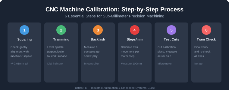
Key Takeaway: Proper CNC machine calibration is essential for achieving sub-millimeter precision in machining operations — the six-step process covers squaring, tramming, backlash compensation, steps-per-unit tuning, test cuts, and final verification.
Table of Contents
1. Why CNC Machine Calibration Matters
CNC machine calibration is the process of verifying and adjusting a machine tool’s geometrical accuracy and positioning precision. Without proper calibration, even the most expensive CNC machine will produce parts with dimensional errors, poor surface finish, and inconsistent tolerances. For manufacturers producing everything from aluminum components to wooden parts, calibration directly impacts first-pass yield, material waste, and production cycle times.
The typical CNC machine loses calibration over time due to normal wear, thermal expansion, mechanical shock, and loose fasteners. A machine that was perfectly calibrated at installation may drift by several hundredths of a millimeter within months of operation. Regular CNC machine calibration ensures that your machine continues to produce parts within specification throughout its service life.
Many machinists ignore calibration until they see visible defects, but by then they may have produced dozens of out-of-spec parts. A structured calibration routine performed at regular intervals prevents scrap and rework before it happens.
2. Gantry Squaring
Gantry squaring is the foundation of CNC machine calibration. It ensures that the X and Y axes are perfectly perpendicular to each other — a 90-degree relationship. Even a 0.1-degree error in gantry alignment causes noticeable dimensional errors in parts with features in both axes.
Procedure: Place a precision machinist square (grade B or better) on the machine bed. Mount a dial test indicator (DTI) in the spindle with a magnetic base. Zero the indicator against one leg of the square, then slowly move the axis along the other leg. Read the deviation across the travel distance. The acceptable tolerance for most applications is ±0.01 mm per 100 mm of travel.
If deviation exceeds tolerance, loosen the gantry mounting bolts slightly and adjust using opposing jacking screws or shim stock. Retighten and re-measure. This process may require several iterations to achieve acceptable alignment.
For machines with rack-and-pinion drives, also check for rack alignment. The rack must be parallel to the axis travel within ±0.05 mm per meter. Misaligned racks cause periodic positioning errors and accelerate pinion wear.
3. Spindle Tramming
Spindle tramming refers to adjusting the spindle so it is perfectly perpendicular to the machine table surface. A trammed spindle ensures that cutting forces are distributed evenly across the tool, producing flat surfaces and reducing tool wear.
To check tram, mount a dial indicator in the spindle with the tip contacting the table surface. Rotate the spindle 180 degrees by hand and observe the reading change. The difference should be less than 0.02 mm for general machining and less than 0.01 mm for precision work.
Adjust tram by shimming the spindle mounting plate or adjusting set screws on the spindle bracket. Tram in the X direction first, then Y, as Y adjustments can affect X alignment. Always perform final verification after tightening all bolts.
4. Backlash Compensation
Backlash is the play or lost motion in a CNC machine’s drive train, primarily from leadscrew nut clearance and coupling compliance. When the machine reverses direction, it must take up this slack before the tool begins moving again. Without compensation, backlash causes rounded corners, incorrect hole positions, and poor surface finish on contour cuts.
Measuring backlash: Mount a dial indicator against the machine table or quill. Jog the axis by 0.1 mm in one direction, note the indicator reading, then jog 0.1 mm in the opposite direction. The difference between expected and actual movement is the backlash value. Repeat at multiple positions along each axis as backlash can vary with screw wear.
Enter the measured backlash values in your CNC controller’s parameters. In LinuxCNC, this is done in the [AXIS_X] section of the INI file. In Mach3/4, backlash compensation is set in Motor Tuning. Grbl-based controllers use the $_backlash parameter ($130 for X, $131 for Y, $132 for Z).
For ball screw driven machines, backlash should be under 0.03 mm when properly maintained. Values above 0.05 mm indicate worn nuts that may need replacement.
5. Steps-Per-Unit Calibration
Steps-per-unit calibration determines how many motor steps the controller must send to move the axis exactly one millimeter or inch. This is the most impactful adjustment in CNC machine calibration for final part accuracy.
Process: Command the machine to move exactly 100 mm (or 10 inches) along one axis. Measure the actual distance traveled using a high-quality steel ruler or calibration standard. Calculate the correction factor: (Expected distance / Actual distance) × Current steps-per-unit.
For example, if your X axis is set to 200 steps/mm and it moves 99.5 mm when commanded to move 100 mm, the corrected value is (100 / 99.5) × 200 = 201.005 steps/mm.
Update the controller with the corrected value and repeat the measurement to confirm accuracy. Achieve ±0.02 mm per 100 mm for hobby machines and ±0.005 mm per 100 mm for industrial machines.
6. Test Cuts and Verification
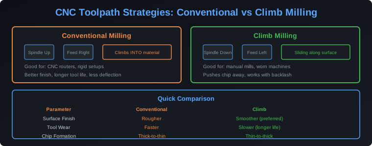
After completing all CNC machine calibration adjustments, perform a test cut to validate real-world accuracy. The most common test is the “circle-diamond-square” test:
- Cut a 50 mm square in your chosen material
- Cut a 50 mm diameter circle inside the square
- Cut a diamond pattern connecting the square corners
- Measure all dimensions with calipers or a micrometer
Compare measured values to expected values. Errors in square dimensions suggest steps-per-unit or backlash issues. Non-circular circles indicate tramming problems. Mismatched diagonal lengths point to gantry alignment errors.
Document all calibration results in a logbook. This historical data helps identify wear trends and predict when components need replacement. Many CAM software packages can generate calibration test G-code automatically.
7. Calibration Schedule
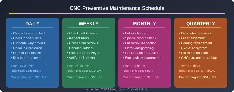
A regular CNC machine calibration schedule prevents quality drift. For production environments:
- Daily: Visual inspection, chip clearance, lubrication check
- Weekly: Test cut on reference material, backlash check
- Monthly: Full calibration procedure including tram and steps-per-unit
- Quarterly: Ball bar test for circular interpolation accuracy
- Annually: Full geometric alignment including laser interferometer verification
Frequently Asked Questions
How often should I calibrate my CNC machine?
Monthly full calibration is recommended for actively used production machines. Weekly backlash checks catch developing issues early. Machines in light use may need calibration only quarterly.
Can I use a laser for CNC machine calibration?
Yes, laser interferometers provide the highest accuracy for CNC machine calibration. They can measure linear positioning accuracy to ±0.001 mm and are the standard for industrial machine tool certification.
What tools do I need for basic CNC calibration?
A dial test indicator (0.01 mm resolution), magnetic base, precision machinist square (grade B or better), and a high-quality steel ruler or gauge blocks are essential for basic CNC machine calibration.
Does thermal expansion affect calibration?
Yes, significantly. Always perform CNC machine calibration when the machine is at operating temperature — typically after 30-60 minutes of runtime. Steel machines grow approximately 0.011 mm per meter per 10°C temperature change.
Related Reading
Sources
- NIST – Manufacturing Standards
- LinuxCNC Documentation – Calibration
- McMaster-Carr – Machinist Squares
- Haas CNC – Calibration Guide
Disclosure: This post contains affiliate links. We may earn a commission on qualifying purchases at no additional cost to you.