Key Takeaway: Spindle speed controls how fast the tool rotates, feed rate controls how fast it moves through the material, and chip load ties them together – understanding cnc feeds and speeds formulas is the fastest way to cut cycle time, protect tooling and improve surface finish.
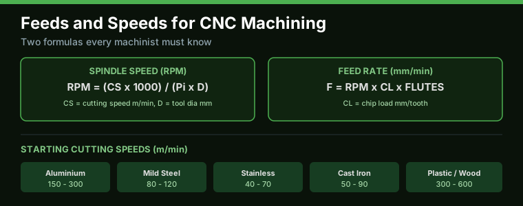
Table of Contents
- 1. What Are Feeds and Speeds and Why They Matter
- 2. Spindle Speed (RPM): The Formula
- 3. Feed Rate: The Formula
- 4. Chip Load: The Foundation of Feeds
- 5. Starting Parameters for Common Materials
- 6. How Toolpaths Change Feeds and Speeds
- 7. Using Feeds and Speeds Calculators
- 8. Common Mistakes and How to Avoid Them
- 9. FAQ
- 10. Related Reading
- 11. Sources
1. What Are Feeds and Speeds and Why They Matter
Feeds and speeds are the two numbers that define how a cutting tool engages the material. Spindle speed (expressed in RPM) is how fast the cutter rotates. Feed rate (expressed in mm/min or IPM) is how fast the cutter moves through the work. Together with depth of cut they determine material removal rate, tool life, surface finish and machining cost.
Set them too slow and you waste hours of cycle time and rub the tool against the material, generating heat that wears the edge without cutting. Set them too fast and you chip or break the tool, ruin the surface, or stall the spindle. Getting cnc feeds and speeds right is therefore the single highest-leverage skill in CNC machining – and it is completely predictable once you understand three formulas.
In this guide we will build the calculations from first principles, give you starting tables for common materials, and show how CAM software such as Fusion 360 applies the same logic automatically.
2. Spindle Speed (RPM): The Formula
Spindle speed is derived from the recommended cutting speed of the tool-and-material combination. Cutting speed (often written CS or Vc) is the velocity of the cutting edge measured in metres per minute (m/min). The relationship is:
RPM = (CS x 1000) / (Pi x D)
where CS is cutting speed in m/min, D is the tool diameter in mm, and Pi is 3.1416. The 1000 converts millimetres to metres. Notice the inverse relationship: a smaller tool must spin faster than a larger tool at the same cutting speed. A 6 mm end mill at 200 m/min must run at about 10,600 RPM, while a 20 mm end mill at the same cutting speed runs at only about 3,180 RPM.
Cutting speed tables are published by every tool manufacturer and depend mainly on the work material and the tool coating. Carbide tools run roughly 2-3 times faster than HSS. When in doubt, start at the lower end of the recommended range – you can always speed up, but a broken tool costs far more than a few extra minutes.
3. Feed Rate: The Formula
Feed rate is calculated from spindle speed, the number of flutes on the tool, and the chip load:
Feed (mm/min) = RPM x Chip Load (mm/tooth) x Number of Flutes
For example, a 4-flute carbide end mill running at 8,000 RPM with a chip load of 0.05 mm/tooth feeds at 8,000 x 0.05 x 4 = 1,600 mm/min. Double the flutes and you double the feed for the same chip load.
The critical insight is that feed rate is a result, not an input. You do not choose a feed rate directly – you choose a chip load that suits the operation and material, then let the formula compute the feed. Chip load is the number that encodes the real machining decision.
4. Chip Load: The Foundation of Feeds
Chip load is the thickness of material removed by each cutting edge per revolution, measured in mm/tooth. It is the single most important value in feeds and speeds because it directly determines cutting force, heat generation and tool wear.
If chip load is too low, the edge rubs instead of cutting. Rubbing generates friction heat that destroys carbide edges quickly – the most common cause of premature tool failure on hobby and small-shop CNCs. If chip load is too high, the tool deflects, the edge overloads, and you risk chipping or breaking flutes.
Typical starting chip loads: aluminium with carbide, 0.02-0.06 mm/tooth for small tools up to 0.10 mm/tooth for larger tools; mild steel, 0.03-0.08 mm/tooth; stainless, 0.02-0.05 mm/tooth. Finishing passes use about half the roughing chip load to keep forces low and surface finish good.
5. Starting Parameters for Common Materials
Use these starting cutting speeds as a baseline, then adjust for your machine rigidity and tool condition:
Aluminium: 150-300 m/min with carbide. Run coolant or mist; aluminium welds to sharp edges without lubrication.
Mild steel (EN8/1018): 80-120 m/min with uncoated carbide, higher with TiAlN-coated carbide under coolant.
Stainless steel (304): 40-70 m/min. Requires rigid setup and positive feeds to avoid work hardening.
Cast iron: 50-90 m/min with carbide. Run dry; cast iron is abrasive and coolant can cause thermal shock.
Plastic and wood: 300-600 m/min with sharp 2-flute tools, low chip loads to avoid melting (plastics) or tear-out (wood).
These values assume a rigid machine and good tool holding. A lightweight router or a hobby mill with ER collet runout will need cutting speeds reduced by 20-40%. The tool itself matters too – our end mill selection guide explains how flute count and coating change the optimum parameters.
6. How Toolpaths Change Feeds and Speeds
The same tool can run very different feeds and speeds depending on the operation. Roughing passes take deep cuts at high feed with lower speed. Finishing passes take shallow cuts at reduced feed with full speed for surface quality. Adaptive/trochoidal toolpaths – where the tool runs at a constant small engagement angle and a very high feed – can remove metal faster with lower radial engagement than conventional slotting.
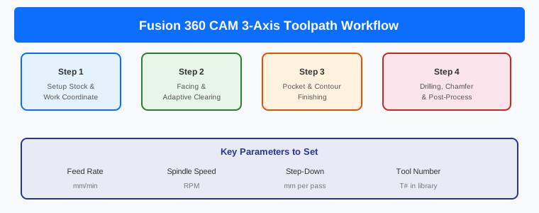
Entry into the material is where tools break. Never plunge a flat-bottom end mill straight down like a drill unless it is centre-cutting and you reduce the feed. Ramp in at 1-3 degrees, or pre-drill a hole, or use a helical entry. Most CAM systems, including the workflows in our Fusion 360 CAM toolpath guide, handle entry moves automatically if you configure them.
Corner conditions also matter. In sharp internal corners the tool engagement increases sharply, so either reduce feed there (CAM feed-optimisation) or use a smaller tool for the corner. Machines with limited rigidity – the kind often built around stepper motors rather than servos – will stall on aggressive corners.
7. Using Feeds and Speeds Calculators
Every serious machinist and CNC programmer should verify manual calculations with a good feeds and speeds calculator. The best calculators take tool diameter, flutes, material, coating and machine rigidity, and return RPM, feed, chip load and even power requirements. Many are free from tool makers like Kennametal and Harvey Tool, and CNC Cookbook maintains a well-known set of calculators and reference charts.
Whatever tool you use, sanity-check the result. If the calculator suggests a feed that your machine physically cannot reach, reduce it and compensate with lighter depth of cut. If you are new to CNC, also check the machine’s spindle and axis limits – our CNC router vs CNC mill comparison covers how machine type changes the practical parameter range.
8. Common Mistakes and How to Avoid Them
Running too slow: The most common beginner mistake. Low chip load causes rubbing, heat and dulled edges. Increase feed until you see proper chips – small, curled chips, not dust.
Ignoring radial engagement: Slotting (full-width cut) at the same parameters as a 30% stepover will overload the tool. Reduce chip load when engagement rises.
Using the same parameters for every material: Aluminium and stainless are opposite extremes. Build a parameter library per material.
Forgetting machine rigidity: Parameters from YouTube videos assume a rigid VMC. A hobby machine needs slower speeds and conservative chip loads.
No coolant strategy: Heat is the enemy of carbide. Flood, mist or at least compressed-air chip clearing changes what the tool can handle. If you machine aluminium, expect the CAD-to-CAM-to-G-code workflow to have you test toolpaths before committing to the machine.
Frequently Asked Questions
How do I calculate cnc feeds and speeds?
First compute spindle speed with RPM = (CS x 1000) / (Pi x D), using the cutting speed for your material. Then compute feed with Feed = RPM x chip load x number of flutes. Chip load is chosen from manufacturer tables for the operation.
What is the difference between cutting speed and feed rate?
Cutting speed is the velocity of the cutting edge (m/min), set by material and tool. Feed rate is how fast the tool advances through the material (mm/min), computed from spindle speed, flutes and chip load.
Why do my tools wear out too fast?
Most often because chip load is too low and the tool is rubbing, or the cutting speed is too high for the material. Check that you are producing proper chips and that the speed matches the material table.
How do feeds and speeds change for aluminium vs steel?
Aluminium runs roughly 2-4 times faster cutting speed than steel and typically uses 2-flute tools to clear chips. Steel needs lower speed and higher rigidity; stainless runs slowest and needs positive feed to avoid work hardening.
Do I still need feeds and speeds if I use CAM software?
Yes. CAM software calculates feeds and speeds from the same formulas, but it uses the material and tool data you give it. If your library is wrong, the CAM output is wrong. Understanding the formulas lets you catch bad results.
Related Reading
- End Mill Selection Guide: Types, Materials and Coatings
- Fusion 360 CAM Guide: Complete CNC Toolpath Workflow
- CNC Router vs CNC Mill Comparison for Indian Workshops
- How to Generate G-code from 3D Models
- Stepper vs Servo Motors for CNC
Sources
- Kennametal: Machining Calculators
- Harvey Tool: Machining Calculators and Formulas
- CNC Cookbook: Feeds and Speeds Guide
- Carbide Depot: Milling Formulas
- Sandvik Coromant: Machining Formulas and Definitions
Disclosure: This post may contain affiliate links. If you purchase through these links, we may earn a commission at no extra cost to you. Recommendations are based on engineering merit, not affiliate revenue.