Key Takeaway: An OpenPnP pick-and-place line pairs open-source software with a stepper-driven XY gantry and a webcam, letting you assemble surface-mount PCBs in-house for under $1000 instead of paying per-board assembly houses.
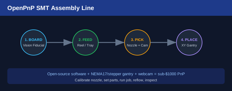
Table of Contents
1. What OpenPnP Actually Is
OpenPnP is free, open-source pick-and-place software. It does not sell hardware — it drives whatever gantry you build. It controls stepper motors for the XY head, a Z axis for nozzle pick height, feeders that present components, and one or more cameras for fiducial alignment and part centering. The software reads your PCB design’s centroid file (from KiCad, Altium or Eagle), matches each part to a feeder, and sequences the placements.
2. Core Hardware: Gantry, Nozzles and Camera
The mechanical heart is an XY gantry: two NEMA17 stepper motors on a belt or lead-screw stage moving a head along X and Y, with a third stepper for Z. A vacuum nozzle on the head picks parts using a small pump. A bottom-view camera identifies each part’s exact offset as it is lifted; a top-view (or board) camera locates fiducials on the PCB so the whole placement map is corrected for board skew.
If you have built CNC equipment before, much of this is familiar — the same stepper control principles appear in multi-axis stepper servo motor controller design. The difference is precision and a vacuum head rather than a spindle.
3. Feeding Parts: Reels, Trays and Cut Tape
Components arrive on reels (tape-and-reel), in trays, or as cut tape. OpenPnP supports all three. Reel feeders advance the tape by a measured pitch so the next component sits under the pick point. You map each feeder slot to a part number in the software, then assign parts to feeders. For prototypes, cut-tape holders are enough; for volume, 8 mm and 12 mm electric feeders speed things up dramatically.
4. Calibration: The Make-or-Break Step
OpenPnP’s calibration wizard walks you through several routines: camera alignment, nozzle offset, feeder vision, and part recognition. Take your time here. A mis-calibrated bottom camera means parts placed millimeters off — invisible to the eye but fatal to the board. Good lighting (a ring LED under the camera) and consistent nozzle tips pay off more than expensive hardware.
5. Running a Job End to End
Load the board, run the bottom camera to confirm fiducials, and hit start. The head moves to a feeder, the nozzle descends, vacuum engages, the part is lifted and recognized, then placed at the corrected XY with the right rotation. A typical two-sided board runs in passes: place the bottom side, reflow, flip, place the top side. For the reflow step, a controlled profile matters — the temperature discipline we cover in PID control with Arduino applies directly to a toaster-oven reflow controller.
6. Reflow and Inspection
After placement, the board goes through a reflow oven or a modified toaster with a PID controller following a lead-free profile. Inspect under a microscope or with the placement camera. OpenPnP logs placement accuracy, so you can catch drift before it becomes scrap.
Frequently Asked Questions
How small a part can OpenPnP place?
With good calibration and a sharp nozzle, 0402 resistors and TSSOP/QFN packages are routine. Sub-millimeter BGAs need a vision upgrade and stencil-printed solder paste.
Do I need a stencil?
Yes for anything past a handful of boards. Solder paste is applied by stencil before placement, so OpenPnP handles paste-printing separately.
Is this faster than an assembly house?
Not for one-off prototypes — setup takes longer than hand-soldering a single board. For repeated small batches it wins on turnaround and cost.
What does the full line cost?
A functional open-source PnP can be built for well under $1000, versus several thousand for an entry closed-source desktop machine.
Related Reading
- Multi-Axis Stepper Servo Motor Controller Design
- PID Control with Arduino
- Best Soldering Stations for Beginners
Sources
Disclosure: This post contains affiliate links. If you buy through them, justLast.in may earn a commission at no extra cost to you.