Key Takeaway: Choosing the right CAD file format — usually STEP, sometimes Parasolid, rarely IGES or STL — prevents broken geometry, wasted CAM time, and scrapped parts when moving designs between CAD and CAM software.
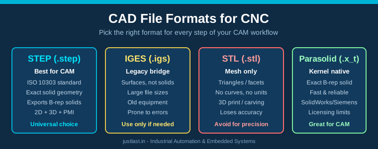
Table of Contents
1. Why CAD File Formats Matter for CNC
Every time a design moves from one piece of software to another — from a customer’s CAD package to your CAM system, or from your modeler to a supplier — it travels through a file format. That format decides whether your CAM software sees a clean, watertight solid or a patchwork of broken surfaces. For anyone running CNC machines day to day, CAD file formats for CNC are not an academic detail: a bad translation can double your programming time or produce a toolpath that gouges the part.
The core difference between formats is how they store geometry. The two big families are boundary representation (B-rep) solids, which describe a part by its mathematically exact faces, edges and vertices, and tessellated meshes, which approximate a part with thousands of flat triangles. Solid, B-rep data is what modern CAM kernels want, because they can compute clean tool contact, automatic feature recognition and collision-free passes from it. Meshes are approximations and inherit a fixed tolerance.
Below we walk through the four formats you will actually meet in a machine shop — STEP, IGES, STL and Parasolid — what each is good at, and where each will burn you.
2. STEP (.step): The Modern Standard
STEP (STandard for the Exchange of Product model data) is the ISO 10303 family of standards, and for most shops it is the safest default. A STEP file, most commonly ISO 10303-21 with the ‘.step’ or ‘.stp’ extension, stores exact B-rep solid and surface geometry along with product structure information. It is vendor-neutral, which is precisely why it exists: so that a model created in one CAD package can be read faithfully by a completely different one.
What makes STEP especially valuable for CNC work is that modern STEP implementations carry solid bodies cleanly, including advanced face and edge topology. AP203 and AP214 (and the newer AP242 for PMI — Product and Manufacturing Information) cover mechanical 3D design; AP242 additionally carries tolerances, GD&T notes and other PMI that a machinist or inspection engineer actually needs. If you receive a part with a tolerance stack that must be respected, an AP242 STEP file can preserve that intent where a mesh never could.
Practical guidance: when exchanging models between different CAD/CAM vendors, or when sending geometry out to a job shop, STEP is the default you should pick. It is readable by essentially every CAM system — Fusion 360, Mastercam, SolidWorks CAM, FreeCAD and free viewers alike.
3. IGES (.igs): Legacy Data That Still Lives
IGES (Initial Graphics Exchange Specification) is the grandfather of CAD data exchange, developed in the 1980s. Its strength is that enormous archives of drawings and models from older systems exist only as IGES files, and some legacy machines, mold shops and suppliers still ask for it. Its weakness is that IGES represents surfaces, curves and points far more naturally than it represents solid bodies. An IGES file often arrives as a cloud of surface patches with gaps between them, and your CAM software then has to stitch, heal and guess — every guess is a chance for a bad toolpath.
IGES files also tend to be large for what they contain, and the format is prone to subtle translation failures: duplicated edges, open shells and reversed normals. Most CAM packages still import it, but treat it as a bridge format for old data, not as a route you choose voluntarily.
If a customer insists on IGES, ask whether the source system can also export STEP — in most cases it can. When you must work with IGES, budget extra time in your CAM system to inspect the imported body, run healing tools, and verify watertightness before creating toolpaths.
4. STL (.stl): Mesh Models for Printing and Carving
STL (stereolithography) files describe a surface as a triangle mesh — just a list of triangles, with no curve data, no units embedded, and no solid topology. The format was invented for 3D printing, and that is where it belongs. It also shows up in CNC work in two places: for simple 3D carving and engraving operations where precision is not critical, and whenever a designer hands you a mesh they exported from a sculpting or scanned-data pipeline.
STL carries three practical traps for machinists. First, it is an approximation: the mesh resolution sets the maximum achievable accuracy, and if the tessellation is coarse, your toolpaths will follow faceted geometry. Second, STL has no unit metadata — a part can silently arrive in millimetres or inches and be interpreted wrongly. Third, there is no solid information, so CAM feature recognition and many automatic strategies do not work; you are reduced to surface machining. Expect to do cleanup, verify scale, and often remesh or re-model if the part demands tolerance.
5. Parasolid (.x_t): The Kernel-Native Format
Parasolid is a commercial geometric modeling kernel from Siemens, and its native file format (‘.x_t’, ‘.x_b’ for binary) deserves a place in your toolkit because a very large share of the CAM world uses it under the hood — SolidWorks, Siemens NX, and Fusion 360’s modeling core are all Parasolid-based, and Mastercam, GibbsCAM and others import Parasolid directly. Exchange between Parasolid-based systems is extremely faithful: because both ends use the same kernel, you avoid the translation step that breaks STEP and IGES exports from time to time.
The main limitation of Parasolid is licensing. The kernel and its file format are commercial, and by default many formats only read Parasolid data, not write it. You may need a paid export option to hand a Parasolid file to a customer, and some open-source workflows cannot touch it. When both sides have Parasolid, it is often the best choice; when you need a format everyone can read, STEP remains king.
6. How to Choose the Right Format
A simple decision rule covers most shop-floor situations:
- STEP — default for cross-vendor exchange; use AP242 when tolerances and PMI matter.
- Parasolid (.x_t) — best when both CAD and CAM are Parasolid-based and you want zero translation risk.
- IGES — only for legacy data or a legacy machine that cannot accept anything else.
- STL / meshes — acceptable for 3D printing, foam carving and rough visual work; avoid for precision metal parts.
Whichever format you use, add a verification step to your workflow. Before importing into CAM, check the file for watertightness, confirm the unit system, and compare bounding-box dimensions against the drawing. Most CAM packages show you a “check model” or “analysis” pass that flags open edges and self-intersections. Spending two minutes on that check is far cheaper than a crashed tool or a scrapped first article.
Also standardize how you ask suppliers for data. A small moment of friction — asking, “Can you send STEP AP242?” — pays off across every future order, because consistent file formats make your CAM library and feeds-and-speeds work reusable instead of a one-off rescue job.
Frequently Asked Questions
What is the best CAD file format for CNC machining?
STEP is the best general-purpose CAD file format for CNC because it stores exact B-rep solid geometry in a vendor-neutral standard that every major CAM package reads. If both your CAD and CAM systems are Parasolid-based, a Parasolid (.x_t) file is an equally safe and even more faithful choice.
Is STL good enough for CNC?
STL is fine for 3D printing, foam carving and cosmetic engraving, but not for precision machining. Because it is a triangle mesh with no solid topology and no unit metadata, it loses accuracy and blocks automatic feature recognition in CAM.
Why are STEP and IGES different?
STEP (ISO 10303) is designed for exact solid-model exchange and carries PMI and tolerances in modern AP242 versions. IGES is an older surface-oriented format that is prone to gaps and healing work when solid bodies are exchanged.
Do I need to convert files before machining?
Not manually — CAM systems import STEP, Parasolid and IGES directly. But you should always verify the imported body (watertight, correct units, right scale) before generating toolpaths, because translation errors are common enough to be dangerous.
Related Reading
- CAM Post-Processors Explained: How Toolpaths Become Machine Code
- CAM Simulation and Toolpath Verification: Prevent Costly CNC Crashes
- Fusion 360 CAM for CNC: Complete Toolpath Guide for 3-Axis Milling
- FreeCAD vs Fusion 360 vs SolidWorks: Which CAD Software Is Best for CNC
Sources
- ISO 10303 (STEP) — Wikipedia
- Siemens PLM Software — Parasolid Geometry Kernel
- Autodesk Fusion 360 — Supported Import Formats
- 3D Systems — STL File Format History
Disclosure: This post contains affiliate links. If you buy through these links, justlast.in may earn a commission at no extra cost to you.