Key Takeaway: CAM simulation and toolpath verification catch crashes, gouges and collisions in software rather than on steel — a full machine-level simulation before the first run is the single most reliable way to avoid broken tools, scrapped parts and dangerous machine crashes, and it is a best practice every CNC programmer should adopt.
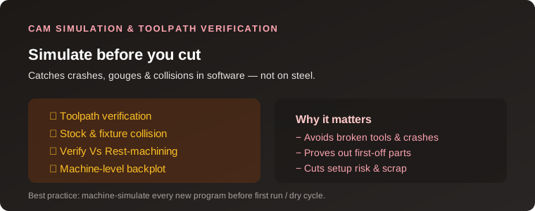
Table of Contents
- 1. Why Simulate Before You Cut
- 2. Toolpath Verification
- 3. Stock and Fixture Collision Detection
- 4. Machine-Level Simulation and Backplot
- 5. Rest Machining and Verify
- 6. A Practical Pre-Run Workflow
- 7. FAQ
1. Why Simulate Before You Cut
Every CNC program is a list of coordinates that the machine will faithfully execute — including the ones you did not mean. A misplaced retract, a wrong coolant default, a tool longer than expected, or a fixture sitting in the path of a rapid move can turn a routine part into a crash that breaks tooling and damages the machine. CAM simulation exists to run that program in software first, so every error shows up on screen instead of as a crash on the shop floor.
The value is both safety and money. Simulating catches the majority of programming mistakes before they reach the machine, which means fewer broken tools, fewer scrapped parts, lighter setup risk and far less downtime. It is standard practice in production machining precisely because it pays for itself the first time it prevents a single crash.
2. Toolpath Verification
Toolpath verification is the basic level: the CAM package shows the tool sweeping material away from a stock model as it follows the toolpath. This reveals gouges, where the tool removes more than the design calls for, and also shows whether the operation actually removes all the intended material. It is available in every mainstream CAM package and is the minimum check any programmer should run.
Watching the toolpath move over the model also makes it easy to spot problems like a tool cutting into a feature it should not, a toolpath that tears through a small delicate wall, or depths that look wrong. At this level you verify geometry and material removal, but you are not yet checking whether the physical machine parts collide.
3. Stock and Fixture Collision Detection
The next step is to include the things physically in the work zone — not just the part, but the stock, the vise, the clamps, and any gear guarding the workpiece. A collision check compares the tool and its holder against these bodies and flags any interference. This catches the classic failure where a tool holder or a spindle nose strikes a tall clamp or a workstop during a rapid traverse, long before a machinist would notice it on screen in a simple toolpath view.
Getting the simulation model right matters: if the fixture bodies in the CAM file do not match what is really on the machine, the collision check gives false confidence. Measure and model the actual vise, clamps and stock position so the check means something real.
4. Machine-Level Simulation and Backplot
The most complete form is machine-level simulation, where the CAM software models the whole machine — spindle, turret or tool changer, table, guards and travel limits — and replays the program against it. This catches collisions between moving machine components, violations of axis travel limits, and tool-change collisions that component-level checks miss. Some packages call this a full machine simulation; others expose it as backplot against a configured machine.
Backplot (visually tracing the generated G-code) is especially useful after post-processing, because it shows what the machine will actually read, including any rapid moves and moves added by the post-processor, rather than only the CAM-internal toolpath. Plotting the posted code catches formatting-induced surprises that the pre-post simulation would not show.
5. Rest Machining and Verify
Two workflow features help you get simulation and programming right. Rest-relative and rest machining (sometimes called “rest mill” or “stock-aware”) lets an operation cut only the material left by previous operations, and verifying this checks that each pass removes exactly what is expected without re-cutting already-finished areas or leaving excess. This both prevents machining air (which wastes time) and prevents an operation from cutting into a feature a previous tool already finished.
Using verify against the actual model each time also keeps the programmer honest about feature integrity — you can confirm that a small hole, a chamfer or a thin rib survives as designed instead of being erroneously removed by a later operation.
6. A Practical Pre-Run Workflow
A reliable workflow is easy to build and easy to repeat. First, verify the toolpath in the CAM package against the part and stock to confirm material removal and hunt for gouges. Second, add the fixture bodies and run a collision check. Third, if your package supports it, run a machine-level simulation to catch travel, tool-change and machine-component collisions. Fourth, post-process and backplot the actual G-code to confirm it matches intent. Finally, run the program on the machine with a dry run — spindle off — before cutting the first part, then cut a first-off in scrap and inspect it.
None of these steps is a substitute for the others; together they are cheap insurance. The minutes spent simulating are trivial compared with the hours lost and the costs incurred by a single crash.
Frequently Asked Questions
What is CAM toolpath verification?
Toolpath verification runs the toolpath in CAM software against a stock model to reveal gouges, confirm material removal and check that the operation cuts what is intended before it reaches the machine.
What is the difference between simulation and verification?
Verification generally checks the toolpath against the part and stock for material removal and gouges. Simulation usually adds the machine components, fixtures and travel limits to also catch collisions.
Does CAM simulation prevent all crashes?
No. It catches the programming errors that occur when the simulation model matches the real machine, but a wrong fixture model or a program edited on the machine can still cause a crash. Use a dry run as well.
Why should I backplot my G-code?
Backplot traces the actual posted G-code, showing rapid moves and post-processor-added motions that a pre-post toolpath simulation does not show, so it catches surprises in the generated program.
What is rest machining?
Rest machining (rest mill or stock-aware) confines an operation to the material left by previous operations, preventing machining air and avoiding cutting into features a previous tool already finished.
Related Reading
Sources
- Autodesk Fusion 360 — Toolpath Simulation and Verification
- Mastercam — Simulation and Verify Resources
- CNC Cookbook — Simulation and Fixture Setup Guides
Disclosure: This post contains affiliate links. If you buy through a link, we may earn a small commission at no extra cost to you. This helps keep justLast.in free for readers.