Key Takeaway: Rigid, repeatable CNC workholding and fixture design — vises, soft jaws, vacuum tables or custom fixtures built in CAD/CAM — is the single biggest lever on accuracy, surface finish and tool life, and it must be planned before you program toolpaths.
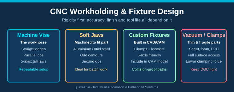
Table of Contents
1. Why Workholding Drives Everything
Walk into any CNC shop and the most experienced machinist will tell you the same thing: a part only ever machines as well as it is held. CNC workholding and fixture design decide how much the workpiece can flex, vibrate or move under cutting force. If the part moves a couple of hundredths of a millimetre during a heavy pass, that error lands in the finished dimension — and no amount of clever toolpath strategy or spindle speed will remove it.
Workholding choices have knock-on effects everywhere. Rigidity determines how aggressive you can be with depth of cut and feed rate, which drives cycle time and tool life. Repeatability determines whether you can run a second operation on every part in a batch without re-probing each one. And the fixture geometry determines how much of the part is accessible to the tool, which shapes the entire CAM plan — including the toolpath strategies you can actually use.
That is why fixture planning belongs at the start of the CAM process, not as an afterthought. The best programmers model the fixture or workholding in their CAD software, include it in the CAM setup, and run simulation with it present so collisions are caught before a crash.
2. The Machine Vise: Your Default Choice
The precision machine vise is the workhorse of CNC workholding, and for good reason. It grips rectangular blanks and parts with a flat, parallel surface on one side of the part, which makes it trivial to fixture workpieces with a machined or sawn reference edge. Vises are fast to set up, highly repeatable from one part to the next, and their jaw faces double as a datum for programming. That combination makes the vise the right default for most milling, drilling and light 3-axis work.
For 5-axis or multi-side work, tall or low-profile jaws keep the part clear of the spindle and table, and double-station and quad-station vises let you load one part while another runs. The classic error with vises is clamping force: too little and the part lifts or shifts; too much on a thin blank and the part bulges upward and distorts when the jaws open. A clean habit is to indicate the part in, and for thin blanks to keep clamping force just above what the cut needs — often called the “kiss” test.
3. Soft Jaws: Machined to Fit the Part
Soft jaws are aluminium or mild-steel jaw inserts bolted to a hard jaw carrier and then machined in place to match the exact contour of the part. Because they are cut with the same machine that will cut the part, soft jaws give you two important properties: a repeatable location relative to the machine axes, and a custom grip profile that supports odd shapes without marring the part.
Soft jaws shine for parts with irregular contours, thin walls, or second operations where you must re-grip the machined profile. You bore a pocket that matches the outside of the finished feature, drop the part in, and machine the opposite face with confidence. They are consumable — you re-cut them for the next job — but the setup time saved on batches usually dwarfs the material cost.
When you design soft jaws in CAD, add a little clearance in the pocket where you do not need contact, but ensure the gripping area is genuinely modelled so your CAM system sees where the part is actually supported. That matters because a pocket drawn without backlash can look rigid in simulation but flex in reality.
4. Custom Fixtures Designed in CAD/CAM
For complex, high-value or high-volume parts, the right answer is a dedicated fixture designed in CAD and machined in your own shop or by a supplier. A custom fixture combines locators — pins, edges and pockets that position the part in a known way — with clamps that hold it. Because the fixture is a machined component, it can index the part for 5-axis access, hold multiple parts per cycle, and be designed with the tool envelope in mind.
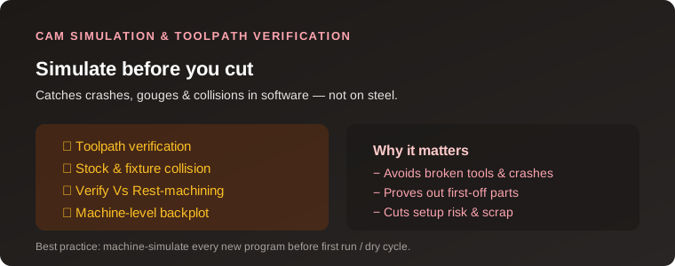
The critical habit is to model the fixture in your CAD assembly and include it as the stock (or a “fixture” component) inside the CAM setup. That one step gives you three huge benefits: collision checking in simulation, toolpath clearance that automatically respects clamps and pins, and the ability to run “verify” passes that would otherwise be unsafe to test on a real machine. This is the same logic that makes CAM simulation and toolpath verification worth doing before every program run.
For small factories and job shops, starting with modular fixturing — a base plate with a grid of tapped holes plus standard locators and clamps — is a practical middle path. You keep the repeatability of a purpose-built fixture without tying up budget in dozens of one-off tools.
5. Vacuum Tables and Clamps for Thin Parts
When the part is thin sheet, foam, acrylic or a PCB panel, conventional clamping either distorts the part or blocks the tool. Vacuum tables hold the workpiece down with air pressure across the whole surface, giving the tool full access to the top face and leaving no clamp in the way. They are the standard solution for sign-making, router work on sheet goods, and thin-plate machining.
The trade-offs are real. Vacuum holding force is modest compared to a vise, so depths of cut must stay light or the part lifts. The work surface must be reasonably flat and free of through-holes that leak vacuum, which is why vacuum fixtures often use thin rubber seals and a gasket pattern matched to the part outline. Alternative low-force options include double-sided tape for very light engraving and toggle or strap clamps around the blank’s edges for thicker work where the middle is still fully accessible.
6. Workholding Best Practices in CAM
Several habits separate layouts that run cleanly from ones that crash or distort:
- Plan the second operation early. Decide in CAM how the part will be flipped or re-gripped, and machine a datum feature in the first op that the second op can use — this is where a well-chosen soft jaw or fixture earns its keep.
- Model the fixture in the CAM assembly. Clamps, pins and jaw bodies included in the model let simulation catch collisions before the spindle does.
- Keep clamping force proportional to the cut. On thin sections, reduce depth of cut rather than over-clamping and distorting the part.
- Use the longest-jaw rule of thumb. Support as much of the part height as the operation allows; unsupported length is where chatter and deflection live.
- Standardise your workholding. The same vise, soft-jaw blank sizes and base plates across jobs make setups faster and tool library organization simpler.
Finally, remember that workholding is a safety topic too. An undermachined clamp that goes unnoticed in simulation is a crash waiting to happen on the floor. Include fixture components in every simulation run, and when in doubt, machine the first article slowly with a conservative toolpath while watching the fixture.
Frequently Asked Questions
What is the best CNC workholding method for a small workshop?
A precision machine vise with a set of soft jaws covers the vast majority of small-shop milling work. Add modular fixturing — a base plate with standard clamps and locators — when you need repeatability for complex or 5-axis parts without machining dedicated fixtures.
How do I stop thin parts from vibrating during CNC workholding?
Support the part over as much of its area as possible, use a vacuum table or soft jaws that contact the whole profile, reduce depth of cut, and lower spindle speeds toward the chatter-free range. The less unsupported length the tool sees, the less vibration you get.
Should workholding fixtures be included in CAM simulation?
Yes, always. Modelling clamps, pins and jaw bodies in the CAM assembly gives you real collision detection before the program runs on the machine, which prevents crashes and scrap parts.
Why does my part distort after machining even though the setup looked rigid?
Distortion usually means internal stress released during machining, or clamping force applied when the part is bowed and released after the jaws open. Try stress-relieving the stock, reducing clamping force, or machining in two passes with a rest pass.
Related Reading
- Fusion 360 CAM Tool Library Setup: Organize Tools, Templates and Workholding
- CNC Toolpath Strategies: Conventional vs Climb Milling
- CAM Simulation and Toolpath Verification: Prevent Costly CNC Crashes
- CNC Preventive Maintenance Schedule for Lathes and Mills
Sources
- Haas Automation — CNC Workholding Guide
- CustomPartNet — Manufacturing Process Reference
- Autodesk Fusion 360 — Fixtures and CAM Setup Documentation
- Mastercam — Workholding and Stock Setup in CAM
Disclosure: This post contains affiliate links. If you buy through these links, justlast.in may earn a commission at no extra cost to you.