Key Takeaway: I2C communication is the most common sensor interface in embedded systems, but wiring errors, address conflicts, and voltage mismatches cause 80% of debugging headaches — this guide covers STM32 and Arduino I2C from wiring through advanced debugging.
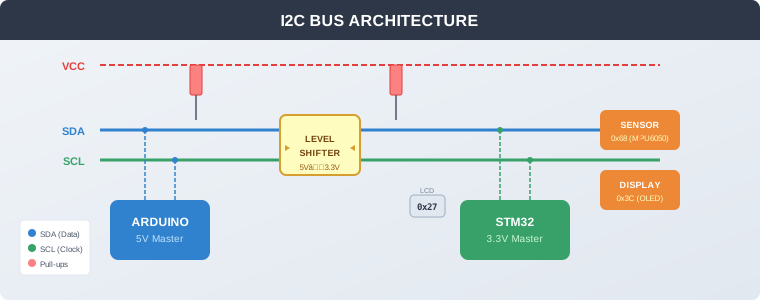
Table of Contents
- 1. What Is I2C and How Does It Work?
- 2. Wiring: SDA, SCL and Pull-Up Resistors
- 3. I2C Addressing: 7-bit vs 8-bit
- 4. STM32 vs Arduino I2C: Key Differences
- 5. Common I2C Problems and Fixes
- 6. Debugging I2C with Logic Analyzers
- 7. Advanced: Clock Stretching, Level Shifting and Bus Extenders
- 8. Frequently Asked Questions
1. What Is I2C and How Does It Work?
I2C (Inter-Integrated Circuit) is a synchronous, two-wire serial communication protocol invented by Philips Semiconductor in 1982. It allows one or more master devices to communicate with multiple slave devices over a shared bus using just two signal lines: SDA (Serial Data) and SCL (Serial Clock).
The protocol is designed for short-distance communication between chips on the same PCB or between nearby modules. Every I2C device has a unique 7-bit address (0x08 to 0x77 for most devices), which the master uses to select which slave it wants to talk to. All other devices on the bus ignore the transaction.
I2C Signal Flow
A typical I2C transaction follows this sequence:
- Start condition: Master pulls SDA low while SCL stays high
- Address byte: Master sends 7-bit address + Read/Write bit (0 = write, 1 = read)
- ACK/NACK: Slave acknowledges by pulling SDA low (ACK) or leaves it high (NACK)
- Data bytes: One or more bytes transferred, each followed by ACK/NACK
- Stop condition: Master releases SDA high while SCL is high
I2C Speed Modes
| Mode | Speed | Max Bus Length | Use Case |
|---|---|---|---|
| Standard Mode | 100 kHz | 1–2 meters | Most sensor projects |
| Fast Mode | 400 kHz | 30 cm | High-speed sensor reading |
| Fast Mode Plus | 1 MHz | Short traces | High-throughput peripherals |
| High-Speed Mode | 3.4 MHz | Very short | Display controllers, camera modules |
For most embedded projects, Standard Mode (100 kHz) or Fast Mode (400 kHz) is sufficient. Higher speeds increase noise sensitivity — keep I2C wires short and use proper pull-up resistor values.
2. Wiring: SDA, SCL and Pull-Up Resistors
Proper wiring is critical for reliable I2C communication. The two most common wiring mistakes — swapped SDA/SCL and missing pull-ups — account for the majority of I2C failures.
The Pull-Up Resistor Rule
I2C uses open-drain outputs. Devices can only pull the bus low — they cannot drive it high. Both SDA and SCL lines need pull-up resistors to hold the lines high when no device is pulling them low.
| Bus Speed | Recommended Pull-Up | Notes |
|---|---|---|
| 100 kHz (Standard) | 4.7 kΩ | Default choice for most projects |
| 400 kHz (Fast) | 2.2–4.7 kΩ | Lower value for faster rise times |
| Long bus (>50 cm) | 2.2 kΩ | Compensates for bus capacitance |
Multiple Pull-Up Problem
Many breakout boards include on-board pull-up resistors. When you connect multiple breakout boards to the same bus, the pull-ups end up in parallel, reducing the effective resistance. If the combined resistance drops too low (below 1 kΩ), the bus devices may not be able to pull the lines low enough for reliable communication.
Fix: Check each breakout board for on-board pull-ups. If multiple boards have them, remove the extra ones or drop the clock speed to 100 kHz.
Pin Mapping: Arduino vs STM32
| Board | Default SDA | Default SCL | Voltage |
|---|---|---|---|
| Arduino UNO | A4 | A5 | 5V |
| Arduino Mega | SDA (pin 20) | SCL (pin 21) | 5V |
| ESP32 | GPIO 21 | GPIO 22 | 3.3V |
| STM32F103 (Blue Pill) | PB7 | PB6 | 3.3V |
| STM32F4 (Nucleo) | PB9 (I2C1) | PB8 (I2C1) | 3.3V |
Critical: Arduino UNO runs at 5V while most modern sensors operate at 3.3V. Connecting a 3.3V sensor directly to a 5V I2C bus can damage the sensor. Use a bidirectional logic level shifter between 5V and 3.3V devices. See our guide on STM32 vs Arduino for industrial automation for more on platform differences.
3. I2C Addressing: 7-bit vs 8-bit
I2C addresses come in two formats that confuse almost every beginner: 7-bit and 8-bit. Understanding the difference prevents hours of debugging.
7-bit Addressing (Arduino Wire Library)
The Arduino Wire library uses 7-bit addresses. The address is simply the value from the device datasheet — no shifting required. The library adds the Read/Write bit automatically as the 8th bit.
// Arduino Wire library — use 7-bit address directly
Wire.beginTransmission(0x3C);  // OLED display at 0x3C
Wire.write(0x00);              // Command byte
Wire.endTransmission();
8-bit Addressing (Some Datasheets)
Some datasheets (especially from ST, TI, and NXP) list 8-bit addresses that include the Read/Write bit. To convert 8-bit to 7-bit, shift right by 1:
// If datasheet says 0x78 (8-bit write address):
uint8_t seven_bit_addr = 0x78 >> 1;  // = 0x3C

// STM32 HAL uses 8-bit (left-shifted) addresses:
HAL_I2C_Master_Transmit(&hi2c1, 0x78, data, len, timeout);
Address Conflict Resolution
When two devices share the same address (common with multiple identical sensors), you have three options:
- Address pins: Many sensors have A0/A1/A2 pins that let you change the address by tying them HIGH or LOW
- Solder jumpers: Some breakout boards have address-select jumpers
- I2C multiplexer: The TCA9548A gives you 8 separate I2C channels — activate one at a time so identical devices on different channels never conflict
For a quick way to find all device addresses on your bus, run an I2C scanner before writing your main program.
4. STM32 vs Arduino I2C: Key Differences
Arduino and STM32 take very different approaches to I2C. Understanding the differences helps you choose the right platform and debug issues faster.
| Feature | Arduino (Wire Library) | STM32 (HAL/I2C) |
|---|---|---|
| Address format | 7-bit (direct) | 8-bit (left-shifted) |
| API style | Simple begin/endTransmission | HAL_I2C_Master_Transmit/Receive |
| Timeout handling | Built-in (limited) | Configurable TIMEOUTR register |
| Clock stretching | Always supported | Configurable (can be disabled) |
| Interrupt mode | Wire.onReceive/onRequest | HAL_I2C_Master_Transmit_IT |
| DMA support | No | Yes (HAL_I2C_Master_Transmit_DMA) |
| Bus recovery | Manual bit-bang required | SWRST bit + manual bit-bang |
Arduino Wire Library Quick Reference
#include <Wire.h>

void setup() {
  Wire.begin();           // Join as master
  Wire.setClock(400000);  // Fast mode (optional)
}

void loop() {
  // Write to slave at 0x3C
  Wire.beginTransmission(0x3C);
  Wire.write(0x00);       // Register address
  Wire.write(0xFF);       // Data byte
  Wire.endTransmission();

  // Read 6 bytes from slave at 0x68 (MPU6050)
  Wire.beginTransmission(0x68);
  Wire.write(0x3B);       // Starting register
  Wire.endTransmission(false);  // Repeated start
  Wire.requestFrom(0x68, 6);

  while (Wire.available()) {
    byte b = Wire.read();
    // Process data
  }
}
STM32 HAL Quick Reference
// STM32 HAL I2C — 8-bit addressing (left-shifted)
uint8_t txData[2] = {0x00, 0xFF};
uint8_t rxData[6];
// Write to slave at 0x3C
HAL_I2C_Master_Transmit(&hi2c1, 0x3C << 1, txData, 2, 1000);
// Read from MPU6050 at 0x68
uint8_t reg = 0x3B;
HAL_I2C_Master_Transmit(&hi2c1, 0x68 << 1, ®, 1, 1000);
HAL_I2C_Master_Receive(&hi2c1, 0x68 << 1, rxData, 6, 1000);For a detailed comparison of STM32 vs Arduino for industrial applications, see our STM32 vs Arduino guide.
5. Common I2C Problems and Fixes
Problem 1: Device Not Found
Symptoms: I2C scanner returns empty list, no devices respond.
Causes and fixes:
- Swapped SDA/SCL: Swap the wires — SDA is data, SCL is clock. They are not interchangeable.
- Missing pull-ups: Measure resistance between SDA/SCL and VCC. Should be 2.2–4.7 kΩ.
- No power: Verify the device has VCC and GND connected with a multimeter.
- Wrong pins: Check your board’s pin mapping table — I2C pins vary between boards.
- Sleeping device: Some sensors start in sleep mode and need a wake-up command before they respond.
Problem 2: Garbled or Corrupt Data
Symptoms: Data arrives but values are wrong or inconsistent.
Causes and fixes:
- Drop clock speed: Set Wire.setClock(100000) for Standard Mode. High-speed over long wires causes errors.
- Wire length: Keep I2C wires under 30 cm for 400 kHz operation.
- Multiple pull-ups: Check for parallel pull-up resistors on breakout boards — remove extras.
- Noise: Add 100nF decoupling capacitors near the device VCC pins.
Problem 3: Bus Locked Up (SDA Stuck Low)
Symptoms: SDA line stays low permanently, no communication possible.
Causes: An interrupted transaction leaves the slave holding SDA low, waiting for clock pulses that never come.
Recovery sequence:
- Release SDA (set as input or pull high)
- Toggle SCL 9 times to clock out the stuck byte
- Generate a STOP condition (SDA low→high while SCL high)
- Re-initialize I2C
Problem 4: Voltage Mismatch
Symptoms: Device works intermittently or is damaged.
Causes: Arduino UNO runs at 5V. Most modern sensors (MPU6050, BMP280, SSD1306) run at 3.3V.
Fix: Use a bidirectional logic level shifter (TXB0104 or BSS138-based module) between the 5V master and 3.3V slaves. Never connect 3.3V devices directly to a 5V bus.
Problem 5: STM32 Clock Stretching Timeout
Symptoms: HAL returns HAL_ERROR or HAL_TIMEOUT during I2C transaction.
Causes: Slave holds SCL low during internal processing (common with SHT3x sensors and custom I2C slaves). STM32’s TIMEOUTR register triggers before the slave finishes.
Fix: Configure TIMEOUTR to 2–3× the slave’s maximum stretch time. Do not blindly increase the timeout — measure the actual stretch duration with a logic analyzer first.
For CAN bus and other industrial communication protocols, see our CAN bus guide.
6. Debugging I2C with Logic Analyzers
When code-level debugging is not enough, a logic analyzer or oscilloscope on the SDA and SCL lines reveals exactly what is happening on the bus.
What to Look For
- Start/Stop conditions: Verify they occur at the right times
- ACK bits: After each byte, check if the 9th clock cycle has SDA low (ACK) or high (NACK)
- Rise times: SDA and SCL should transition from 30% to 70% of VCC within the I2C spec (1000ns for Standard Mode, 300ns for Fast Mode)
- Clock stretching: SCL held low by slave — measure the duration
- Address byte: Verify the 7-bit address + R/W bit matches what you intended
Using ESP32 Bit Pirate as I2C Analyzer
The ESP32 Bit Pirate firmware (covered in our ESP32 Bit Pirate review) can sniff I2C traffic passively. Connect it between the master and slave, enter I2C sniff mode, and watch live traffic without interfering with the bus.
Arduino I2C Scanner Code
Before using a logic analyzer, run this scanner to quickly identify connected devices:
#include <Wire.h>

void setup() {
  Wire.begin();
  Serial.begin(115200);
  Serial.println("I2C Scanner");
}

void loop() {
  for (byte addr = 1; addr < 127; addr++) {
    Wire.beginTransmission(addr);
    byte error = Wire.endTransmission();
    if (error == 0) {
      Serial.print("Device found at 0x");
      Serial.println(addr, HEX);
    }
  }
  delay(5000);
}
7. Advanced: Clock Stretching, Level Shifting and Bus Extenders
Clock Stretching
Clock stretching is an optional I2C feature where the slave holds SCL low to tell the master to wait. Common in sensors that need time for ADC conversion (like the SHT3x temperature/humidity sensor) and in software I2C slaves running on microcontrollers.
On STM32, clock stretching can be disabled via the NOSTRETCH bit — but this violates the I2C specification and may cause data corruption with compliant slaves. Only use it with known-compatible devices.
Level Shifting for Mixed-Voltage Systems
When mixing 5V and 3.3V devices on the same bus, a bidirectional level shifter is essential. The most common options:
- TXB0104: Auto-direction sensing, no direction pin needed. Good for most I2C applications.
- BSS138-based modules: Cheaper, widely available, works reliably at I2C speeds.
- PCA9306: Dedicated I2C level shifter with built-in pull-ups. Best choice for production designs.
Bus Extenders for Long Runs
Standard I2C is limited to about 30 cm at 400 kHz. For longer distances:
- P82B96: I2C bus extender that doubles the range to several meters
- PCA9600: Dual bidirectional bus buffer for long cable runs
- CAN bus or RS-485: For distances over 10 meters, consider converting I2C to a differential bus
8. Frequently Asked Questions
Can I connect 5V and 3.3V I2C devices on the same bus?
Yes, but only with a bidirectional logic level shifter between them. Never connect 3.3V devices directly to a 5V bus — the higher voltage can damage the 3.3V device’s I2C pins. A BSS138-based level shifter module costs less than $1 and solves this permanently.
How many devices can I connect to one I2C bus?
Theoretically 127 devices (7-bit address space). In practice, bus capacitance limits you to about 10–20 devices at 100 kHz with standard wiring. Each device adds capacitance that slows signal rise times. Use an I2C multiplexer (TCA9548A) if you need more devices.
Why does my I2C device stop responding after a few minutes?
Common causes: loose breadboard connections, electrical noise from motors or switching power supplies, or the device overheating. Check connections with a multimeter, add 100nF decoupling capacitors near the device, and ensure the device is within its operating temperature range.
What is the difference between I2C and SPI?
I2C uses 2 wires (SDA, SCL) and supports multiple slaves with addressing. SPI uses 4 wires (MOSI, MISO, SCK, SS) and is faster but requires a separate chip select line per slave. Use I2C for simple sensor connections with few devices. Use SPI when you need speed (displays, SD cards) or have many devices.
How do I recover a locked I2C bus on STM32?
Toggle SCL manually 9 times while SDA is released, then generate a STOP condition (SDA low→high while SCL is high), and re-initialize the I2C peripheral. The STM32 HAL’s SWRST bit alone is not sufficient if the slave is physically holding SDA low — you must bit-bang clock pulses.
Related Reading
- STM32 vs Arduino for Industrial Automation: Complete 2026 Guide
- ESP32 Bit Pirate 2026: The Open-Source Multi-Protocol Debug Tool
- CAN Bus for Industrial Systems: Reliable Multi-Node Communication
- VFD Motor Speed Control: Complete Installation Guide
Sources
- Texas Instruments — How to Debug I2C (Application Note SCPA063)
- embeddedSoft — Fixing I2C Clock Stretching Timeouts on STM32
- ST Community — How to Use I2C with STM32CubeMX2
- Controllers Tech — Arduino I2C Tutorial: Wire Library, Master, Slave & Scanner
Disclosure: This post contains affiliate links. If you purchase through these links, we may earn a commission at no additional cost to you. Our recommendations are based on independent research and testing.