Key Takeaway: A Variable Frequency Drive (VFD) gives you precise spindle speed control on CNC machines, but incorrect setup can destroy both the VFD and your spindle motor — follow this tuning guide to get it right the first time.
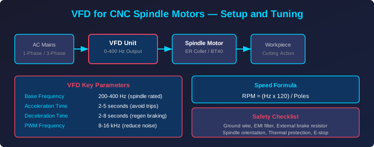
Table of Contents
1. What Is a VFD and Why CNC Spindles Need One
A Variable Frequency Drive, commonly known as a VFD, is an electronic device that controls the speed of an AC motor by varying the frequency and voltage of the electrical supply. In CNC machining, the spindle motor is the heart of the cutting operation — it spins the end mill, drill, or router bit that removes material from the workpiece. Without a VFD, you would be limited to running the spindle at a fixed speed, which severely restricts the range of materials and operations you can perform.
The VFD takes standard 50 or 60 Hz mains power and converts it to a variable output frequency, typically ranging from 0 to 400 Hz or higher for high-speed spindles. This conversion is done through a process called Pulse Width Modulation (PWM), where the VFD rapidly switches the output voltage to simulate a sine wave at the desired frequency. By changing the frequency, you directly control the rotational speed of the spindle motor.
For CNC applications, the VFD serves several critical functions. First, it enables constant torque operation at lower speeds for heavy cutting in steel and stainless materials. Second, it allows high-speed operation — many air-cooled spindles run at 24,000 RPM or more — for fine finishing passes in aluminum and plastics. Third, the VFD provides built-in motor protection against overcurrent, overvoltage, and thermal overload, which protects your expensive spindle from damage.
2. Choosing the Right VFD for Your Spindle
Selecting the correct VFD for your CNC spindle is not optional — a mismatched VFD will either fail to deliver full power or worse, damage the motor. The three most critical specifications to match are voltage rating, current capacity, and power rating.
Voltage rating must match your spindle motor. Most CNC spindles operate at 220V single-phase or 380V three-phase. If your spindle is rated for 220V three-phase, you need a VFD that can output three-phase power from a single-phase input — this is common in home workshop environments where three-phase mains power is unavailable. These single-phase input, three-phase output VFDs are specifically designed for CNC applications.
Current capacity is where many builders make mistakes. The VFD must be rated for at least 120% of the spindle motor’s rated current. For example, if your spindle draws 5A at full load, choose a VFD rated for at least 6A. This headroom accounts for startup surges and momentaneous overloads during heavy cuts. Brands like Huanyang, Dawer, and GD300 are popular choices in the CNC community, with the Huanyang 2.2 kW model being a proven performer for most desktop and mid-size CNC routers.
Power rating should match or exceed your spindle’s power consumption. Common CNC spindle ratings are 0.8 kW, 1.5 kW, 2.2 kW, and 3.0 kW. Always cross-reference the spindle manufacturer’s datasheet with the VFD’s specifications to ensure compatibility.
3. Wiring and Electrical Setup
Incorrect wiring is the number one cause of VFD and spindle failure. Follow these steps precisely, and if you are not comfortable with mains electrical work, hire a qualified electrician.
Input wiring: Connect your mains supply to the VFD’s R, S, and T terminals. For single-phase operation, connect the live wire to R and leave S and T bridged or connect to the same phase as specified in the VFD manual. Always include a dedicated circuit breaker rated at 150% of the VFD’s input current, and install an EMI filter between the mains supply and the VFD to reduce electromagnetic interference that can affect other electronics in your workshop.
Output wiring: Connect the VFD’s U, V, and W terminals to the spindle motor’s three phase wires. The order of these connections determines the spindle’s rotation direction. If the spindle spins the wrong way, simply swap any two of the three output wires. Never swap wires while the VFD is powered on.
Grounding: This is non-negotiable. Connect the VFD’s ground terminal to both the VFD chassis and the spindle motor housing using a minimum 14 AWG green/yellow ground wire. Poor grounding leads to electrical noise, erratic spindle behavior, and potential shock hazards. In industrial environments, a ground loop with less than 1 ohm impedance is the standard.
Control signals: Most CNC setups use the VFD’s analog input (0-10V) or RS-485 Modbus interface for speed control from the CNC controller. The 0-10V analog input is simpler to set up — connect your controller’s PWM output through a low-pass filter to the VFD’s AI1 terminal. For Modbus control, connect the A+ and B- terminals to your controller’s RS-485 port and configure the VFD’s communication parameters accordingly.
4. Essential VFD Parameters to Configure
Out of the box, a VFD comes with factory default settings that are rarely appropriate for a CNC spindle. You must configure these parameters before first use. The exact parameter numbers vary by VFD brand, but the concepts are universal.
Base frequency (P003 or similar): Set this to your spindle’s rated frequency, typically 400 Hz for high-speed spindles or 50 Hz for standard motors. This tells the VFD the maximum frequency it should output, which directly corresponds to the spindle’s maximum rated RPM.
Maximum frequency (P004): Set this equal to or slightly above the base frequency. Do not set this higher than your spindle’s rated maximum RPM divided by the motor’s pole pairs, as overspeeding a spindle can cause bearing failure and dangerous vibration.
Acceleration time (P010): This controls how quickly the spindle ramps from zero to maximum speed. For most CNC spindles, 2 to 5 seconds is appropriate. Too short an acceleration time causes excessive current draw and may trigger the VFD’s overcurrent protection. Too long wastes time on every tool change and startup.
Deceleration time (P011): Controls the ramp-down time. Set this between 2 and 8 seconds. If your VFD does not have a braking resistor, set a longer deceleration time to avoid overvoltage faults during regenerative braking.
PWM carrier frequency (P072 or similar): This determines the switching frequency of the VFD’s output. Higher values (8-16 kHz) reduce audible whine from the spindle but increase heat generation in the VFD. Lower values (2-4 kHz) are more efficient but produce louder motor noise. For a home workshop, 8 kHz is a good balance.
Motor rated current (P008): Set this to the exact rated current of your spindle motor as printed on the motor nameplate. The VFD uses this value for overcurrent protection, so an incorrect setting can either trip too frequently or fail to protect the motor.
5. Spindle Speed Tuning and Calibration
Even with correct parameters, the VFD’s displayed speed and the actual spindle speed may not match. Speed calibration ensures that when your G-code calls for S18000, the spindle actually spins at 18,000 RPM.
Step 1: Measure actual RPM. Use a digital tachometer — either a contact type with a reflective strip on the spindle shaft, or a non-contact laser tachometer aimed at the rotating shaft. Run the spindle at several known VFD frequencies (100 Hz, 200 Hz, 300 Hz, 400 Hz) and record the measured RPM at each point.
Step 2: Calculate the RPM-per-Hz ratio. For a 2-pole motor, the formula is RPM = (Frequency x 120) / Poles. A 400 Hz, 2-pole spindle should produce 24,000 RPM. If your measurements show 23,200 RPM at 400 Hz, your actual ratio is 58 RPM per Hz. Adjust your G-code sender’s spindle speed settings accordingly.
Step 3: Set the VFD’s frequency scaling. Some VFDs have a parameter that lets you scale the output frequency to match a target RPM. If available, enter your measured RPM-per-Hz ratio so the VFD’s display shows actual RPM instead of frequency. This makes workflow easier since you can think in RPM rather than Hz.
Step 4: Test under load. Speed accuracy at no-load does not guarantee accuracy under cutting load. Run a test cut in a known material at a calculated feed rate and check the surface finish. If the finish shows feed marks that are too wide or too narrow, adjust the spindle speed offset in your CAM software by the measured percentage error.
6. Common Problems and Troubleshooting
Overcurrent fault (OC or E.OC): This typically means the acceleration time is too short, the VFD is undersized for the spindle, or there is a short in the motor wiring. Increase the acceleration time first. If the fault persists, check wiring for shorts and verify the VFD’s current rating exceeds the spindle’s rated current.
Overvoltage fault (OV or E.OV): This occurs during rapid deceleration when the motor acts as a generator and feeds energy back into the VFD. Install a braking resistor across the VFD’s B+ and B- terminals, or increase the deceleration time to allow the energy to dissipate more slowly.
Spindle runs but vibrates excessively: Check the collet and tool for runout using a dial indicator. Vibration can also result from a worn spindle bearing, unbalanced tooling, or incorrect VFD parameters causing harmonic resonance. Try changing the PWM carrier frequency to shift the harmonic content away from the spindle’s natural frequency.
Spindle does not reach commanded speed: Verify the VFD’s maximum frequency parameter matches your spindle’s rated frequency. Check that the 0-10V analog control signal actually reaches 10V at maximum commanded speed. A common mistake is a voltage divider in the control circuit that limits the signal to 5V, which would halve the maximum spindle speed.
Frequently Asked Questions
Can I use a standard VFD for my CNC spindle?
Yes, but the VFD must be rated for the spindle’s voltage, current, and frequency range. Standard industrial VFDs designed for general-purpose motor control can drive CNC spindles if the specifications match. However, purpose-built CNC spindle VFDs often include features like automatic tool-length sensing and spindle orientation that generic VFDs lack.
What happens if I overspeed my spindle?
Running a spindle beyond its rated maximum RPM causes excessive bearing wear, increased vibration, and potential catastrophic failure where the spindle can come apart at high speed. This is a serious safety hazard. Always set the VFD’s maximum frequency to match the spindle’s rated maximum RPM and enable the VFD’s overspeed protection.
Do I need a braking resistor for my CNC VFD?
A braking resistor is recommended if you need rapid spindle deceleration — for example, during tool changes or emergency stops. Without a braking resistor, you must set longer deceleration times to avoid overvoltage faults. For most hobby CNC setups, longer deceleration times are acceptable, and a braking resistor is optional.
How do I control spindle speed from my CNC controller?
The two most common methods are analog voltage control (0-10V) and digital Modbus communication. Analog control is simpler — your controller outputs a voltage proportional to the desired speed, and the VFD interprets this as a frequency command. Modbus provides more control and feedback but requires software configuration. Most GRBL and LinuxCNC setups use analog control, while Mach4 and Masso support both.
Related Reading
- CNC End Mills and Tooling: Complete Guide to Flute Count, Coatings and Feeds
- CNC Machine Calibration: Complete Guide to Squaring, Tramming and Backlash Compensation
- Complete Guide to CNC Milling Operations: Face, Slot, Contour and Pocket Milling
- PID Control with Arduino: Closed-Loop Temperature and Motion Control Guide
Sources
- Instructables — Setting Up a VFD for a CNC Spindle
- Huanyang VFD — Parameter Setting Guide
- Shapeoko Wiki — Spindle Setup and Configuration
- Reichelt — VFD Variable Frequency Drive Technical Guide
- V1 Engineering Forum — VFD Setup for CNC Spindle
Disclosure: This post contains affiliate links. If you purchase through these links, we may earn a commission at no additional cost to you.