Key Takeaway: STM32 PWM is the backbone of motor control in industrial automation — advanced timers generate precise pulse trains for servo, stepper, and BLDC drives, and mastering prescaler/ARR/CCR math lets you set exact frequency and duty cycle for any motor.
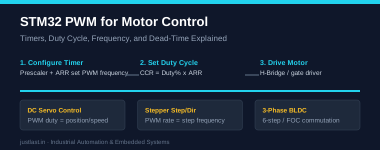
Table of Contents
1. Why STM32 PWM Matters for Motor Control
In a factory automation environment, motors do the physical work and the microcontroller decides how precisely that work is done. STM32 PWM output determines motor speed, torque, position, and acceleration profile. Unlike a simple Arduino bit-bang approach, STM32 timers generate PWM in hardware with zero CPU load once configured — the timer counts independently and toggles output pins on exact compare events. This is essential when you are simultaneously running a motion-control loop, reading encoders, and talking to an HMI over Modbus.
The STM32 family gives you general-purpose timers (TIM2, TIM3, TIM4, TIM5) and advanced-control timers (TIM1, TIM8) designed specifically for motor drives. The advanced timers add features like complementary outputs and programmable dead-time, which are mandatory for driving half-bridge and H-bridge power stages safely.
2. How an STM32 Timer Generates PWM
Every STM32 PWM channel is built from a counter that runs at a clock frequency and compares its value against one or more registers. The three registers you must understand are:
PSC (Prescaler) — divides the timer clock down to a counting frequency. ARR (Auto-Reload Register) — sets the maximum counter value and therefore the PWM period. CCR (Capture/Compare Register) — holds the compare value that sets the duty cycle.
When the counter is in up-counting mode, it counts from 0 to ARR, resets, and repeats. The output pin goes HIGH when the counter is below CCR and LOW when it reaches or exceeds CCR (in PWM mode 1). The result is a square wave whose frequency is set by PSC and ARR, and whose duty cycle is set by CCR.
3. Setting PWM Frequency with Prescaler and ARR
The core formula for STM32 PWM frequency is:
PWM_Frequency = Timer_Clock / ((PSC + 1) x (ARR + 1))
For example, with a 72 MHz timer clock on an STM32F103: to generate a 20 kHz PWM you choose PSC = 0 and ARR = 3599, because 72,000,000 / (1 x 3600) = 20,000 Hz. To generate a 50 Hz servo signal instead, use PSC = 71 and ARR = 19999, giving 72,000,000 / (72 x 20000) = 50 Hz. The beauty of this arrangement is that frequency stays rock-solid regardless of what the CPU is doing, because the timer is a peripheral running in parallel.
4. Controlling Duty Cycle with CCR
Once the frequency is fixed by PSC and ARR, the duty cycle is simply the CCR value divided by ARR:
Duty_Cycle (%) = CCR / ARR x 100
So with ARR = 3599, a CCR of 1800 gives exactly 50% duty, and a CCR of 360 gives 10%. For motor control you typically drive an H-bridge or gate driver chip: the PWM duty maps to the average voltage applied to the motor, and the average voltage maps to speed for a DC motor or to holding torque / position increment for a stepper. To change speed smoothly you write a new CCR every update — the timer applies it at the next reload, producing glitch-free transitions.
5. PWM Modes for Motor Drives
Beyond basic PWM mode 1, STM32 timers support several output configurations useful in motor control:
PWM mode 1 vs mode 2 — Mode 1 is active while the counter is below CCR; mode 2 is the inverse. Mode 1 is the standard choice for most drives.
Center-aligned PWM — The counter counts up and down, producing a symmetric waveform. Center-aligned mode gives lower harmonic distortion in three-phase inverters and is preferred for FOC and BLDC commutation.
Complementary outputs with dead-time — TIM1 and TIM8 generate CH1 and CH1N (complementary) with a programmable insertion delay, which prevents shoot-through in half-bridges.
One-pulse mode — Generates a single controlled pulse, useful for precise stepper step commands or testing.
6. Dead-Time Insertion for H-Bridges
When an H-bridge switches direction, the high-side and low-side transistors on the same leg must never be on at the same time — that creates a short circuit called shoot-through. STM32 advanced timers insert a dead-time between the turn-off of one transistor and the turn-on of the complementary one. Typical dead-time for a MOSFET gate driver is 0.5 to 2 microseconds. In STM32CubeMX you set the dead-time in the Break and Dead-Time settings of TIM1/TIM8, and the hardware enforces it on every edge. This is a safety-critical feature that a software-only bit-bang PWM cannot reliably provide.
7. Step-by-Step STM32 PWM Motor Example
Here is a minimal example using STM32Cube HAL to output 20 kHz PWM on TIM3 Channel 1 (PA6) with a 50% duty cycle:
TIM_HandleTypeDef htim3;
TIM_OC_InitTypeDef sConfigOC;

__HAL_RCC_TIM3_CLK_ENABLE();

htim3.Instance = TIM3;
htim3.Init.Prescaler = 0;
htim3.Init.CounterMode = TIM_COUNTERMODE_UP;
htim3.Init.Period = 3599;          /* 20 kHz at 72 MHz */
htim3.Init.ClockDivision = TIM_CLOCKDIVISION_DIV1;
HAL_TIM_PWM_Init(&htim3);

sConfigOC.OCMode = TIM_OCMODE_PWM1;
sConfigOC.Pulse = 1800;            /* 50% duty */
sConfigOC.OCPolarity = TIM_OCPOLARITY_HIGH;
HAL_TIM_PWM_ConfigChannel(&htim3, &sConfigOC, TIM_CHANNEL_1);
HAL_TIM_PWM_Start(&htim3, TIM_CHANNEL_1);
Change speed on the fly with __HAL_TIM_SET_COMPARE(&htim3, TIM_CHANNEL_1, newDuty). For a stepper motor you would instead use a timer output-compare interrupt or a hardware pulse generator; for a servo, the same STM32 PWM channel at 50 Hz with a 0.5–2.4 ms pulse width maps directly to angular position.
Frequently Asked Questions
What is the maximum PWM frequency on STM32?
With a 72 MHz timer clock and ARR = 0, the theoretical maximum is 36 MHz, but practical motor-drive PWM frequencies are 8–40 kHz for DC/BLDC and 50 Hz for servos. Always check the timer clock tree in your STM32 reference manual.
How do I choose the STM32 PWM frequency for a motor?
For audible-noise reduction in small DC and BLDC motors, use 20–40 kHz (above human hearing). For high-torque industrial servos, 8–20 kHz with proper dead-time is common. Slower frequencies cause audible whine and more torque ripple.
Can one STM32 timer drive multiple motors?
Yes. A single timer with multiple channels (TIM3 has 4 channels) can drive up to four DC motors if they share the same frequency. Different frequencies require separate timers, which is why STM32F4/F7 parts have many timers.
What is the difference between STM32 PWM and Arduino PWM?
Arduino PWM runs at fixed frequencies around 490 Hz or 980 Hz using a simplified timer setup, while STM32 PWM is fully programmable in frequency and resolution with hardware dead-time. For industrial motion control this flexibility is the main reason engineers move from Arduino to STM32.
Related Reading
- STM32 vs Arduino for Industrial Automation: Complete 2026 Guide
- DRV8825 vs A4988 vs TMC2209: Stepper Motor Driver Comparison
- I2C Communication Complete Guide for STM32 and Arduino
- MQTT for Industrial IoT: Complete Guide with ESP32 Examples
Sources
- STM32F1 Reference Manual (RM0008) — Timer Section
- STM32CubeMX — Timer and PWM Configuration
- STM32 HAL and Low-Layer Drivers User Manual
Disclosure: This post contains affiliate links. As an Amazon Associate, justlast.in may earn a commission on qualifying purchases at no extra cost to you.