Key Takeaway: I2C communication lets one microcontroller talk to dozens of sensors, displays, and memory chips over just two wires — and getting the pull-up resistors, 7-bit address shifting, and a proper bus scan right solves nearly every I2C problem you will ever hit.
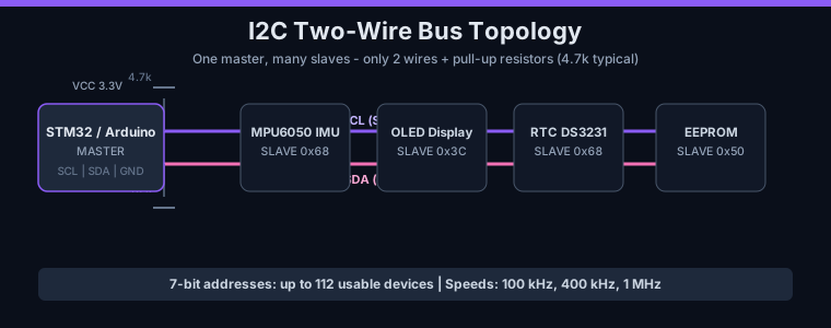
Table of Contents
- 1. I2C Basics: Two Wires, Many Devices
- 2. Pull-Up Resistors: The Most Overlooked Detail
- 3. Addressing and the 7-Bit Shift Gotcha
- 4. The Transaction: Start, Address, ACK, Stop
- 5. I2C Communication on Arduino (Wire Library)
- 6. I2C on STM32 with HAL
- 7. Multiple Devices, Multiplexers, and Bus Hangs
- 8. Troubleshooting Checklist
- 9. FAQ
- 10. Related Reading
- 11. Sources
1. I2C Basics: Two Wires, Many Devices
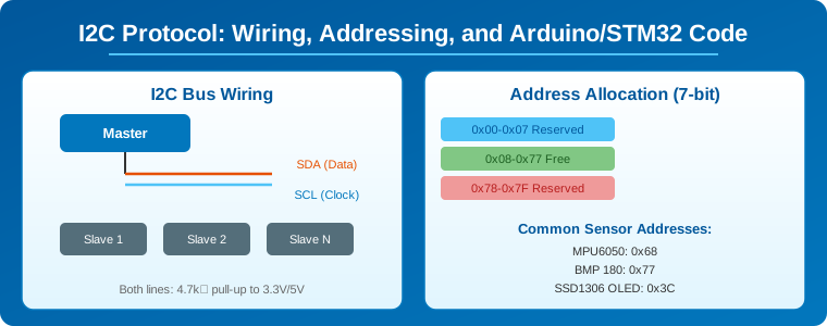
I2C (Inter-Integrated Circuit) was created by Philips in 1982 and remains the dominant short-distance bus for on-board peripherals. It is a two-wire, half-duplex, synchronous serial protocol: the SCL line carries the clock generated by the master, and the SDA line carries bidirectional data. Because every device has a unique address, a single master can talk to up to 112 usable addresses over the same two wires — no chip-select pins needed.
I2C communication shows up everywhere in industrial and maker hardware: the MPU-6050 IMU, DS3231 real-time clock, SSD1306 OLED displays, AT24C series EEPROMs, and I2C LCD backpacks all ride the same bus. For an embedded engineer, I2C is usually the second protocol you learn (after UART) and the first one you debug for hours because a resistor is missing.
2. Pull-Up Resistors: The Most Overlooked Detail
I2C lines use open-drain outputs. Devices can only pull SDA and SCL low — they cannot drive them high. Pull-up resistors to VCC are what bring the lines back high, and without them communication is impossible. This is the single most common I2C failure mode for beginners.
Resistor value depends on bus speed and capacitance. As a rule of thumb: 4.7 k for Standard Mode (100 kHz), 2.2 k to 4.7 k for Fast Mode (400 kHz), and about 1 k for Fast-Mode Plus (1 MHz). Too high a value makes the rise time too slow; too low wastes power and stresses the drivers. One trap: many breakout boards ship with their own pull-ups. Stack several modules and you can end up with too many resistors in parallel, overloading the bus. Keep one set, remove or disable the rest.
3. Addressing and the 7-Bit Shift Gotcha
Standard I2C uses 7-bit addresses, giving 128 possible addresses (0x00–0x7F), of which a few are reserved, leaving 112 usable. Some devices expose address pins — the PCF8574 has A0/A1/A2 giving eight addresses (0x20–0x27); the BMP280 has one pin giving 0x76 or 0x77; the MPU-6050 has AD0 giving 0x68 or 0x69.
The most common bring-up mistake in STM32 HAL is the 7-bit address shift. The HAL functions expect the 8-bit (left-shifted) form: the MPU-6050’s 7-bit address 0x68 must be passed as 0x68 << 1 = 0xD0. Forgetting this produces a NACK on every single transaction. The Arduino Wire library, by contrast, expects the plain 7-bit address and adds the read/write bit itself — which is why code that works on Arduino fails mysteriously when ported to STM32 HAL.
4. The Transaction: Start, Address, ACK, Stop
Every I2C communication transaction follows the same sequence. The master pulls SDA low while SCL stays high (START condition), then clocks out the 7-bit slave address followed by a read/write bit. The addressed slave acknowledges by pulling SDA low for one clock (ACK); if SDA stays high, that is a NACK and nobody answered. Then one or more data bytes are transferred, each acknowledged, until the master ends with a STOP condition (SDA released high while SCL is high).
For register-based sensors, a read usually begins with a write: the master sends the register address, then issues a repeated START and switches to read mode. On STM32 HAL, the memory functions HAL_I2C_Mem_Read() and HAL_I2C_Mem_Write() encapsulate exactly this pattern — use them for 99 percent of sensor drivers instead of manually chaining transmit and receive.
5. I2C Communication on Arduino (Wire Library)
Arduino hides most of the protocol behind the Wire library. The standard pattern for a master:
- Wire.begin() — start as master (or Wire.begin(address) to be a slave).
- Wire.setClock(400000) — switch to Fast Mode.
- Write: Wire.beginTransmission(0x68); Wire.write(reg); Wire.write(value); Wire.endTransmission();
- Read: Wire.requestFrom(0x68, n); while (Wire.available()) { byte b = Wire.read(); }
Pins vary by board: Arduino Uno and Nano use A4 (SDA) and A5 (SCL); the Mega uses 20 and 21; the ESP32 uses GPIO21 and GPIO22 (configurable). Use the 7-bit address directly in Wire.beginTransmission() — the library adds the read/write bit for you.
6. I2C on STM32 with HAL
On STM32, configure the peripheral in STM32CubeMX: enable an I2C instance, set Standard or Fast Mode, and enable internal pull-ups in the GPIO settings (though external pull-ups are still recommended for reliability). Data transfer runs in three modes:
- Blocking: HAL_I2C_Master_Transmit() / HAL_I2C_Master_Receive() — simplest, fine for slow polling.
- Interrupt: HAL_I2C_Master_Transmit_IT() — non-blocking, completion via callback.
- DMA: HAL_I2C_Master_Transmit_DMA() — zero CPU involvement, best for high-throughput logging.
Always run a bus scan during bring-up. HAL_I2C_IsDeviceReady() probes an address and returns HAL_OK when a device ACKs. A scan over all 128 addresses confirms power, pull-ups, and address pins before you write a line of sensor code.
7. Multiple Devices, Multiplexers, and Bus Hangs
Multiple I2C devices share SDA, SCL, and ground; each needs a unique address. When two identical sensors have fixed addresses, use an I2C multiplexer such as the TCA9548A — an 8-channel switch that electrically isolates each downstream bus so identical addresses never collide. Keep the bus short (under 1 m at 100 kHz, under 30 cm at 400 kHz) because wire capacitance degrades the signal.
Bus hangs happen when a slave is mid-byte when the master resets: the slave keeps SDA low waiting for more clocks, and the master can no longer generate a START. The recovery is to bit-bang exactly 9 SCL pulses while watching SDA — this clocks out the slave’s partial byte until it NACKs and releases the line — then issue a STOP and re-initialize the peripheral.
8. Troubleshooting Checklist
- Run an I2C scanner first — if no device appears, check wiring and pull-ups.
- Verify SDA and SCL idle HIGH (measure with a multimeter). If they float low, pull-ups are missing.
- Check address conflicts: two devices on the same address corrupt each other’s traffic.
- Check voltage levels: a 3.3 V sensor on a 5 V bus may need a level shifter.
- Slow the clock: Wire.setClock(50000) or 100 kHz fixes marginal rise-time problems.
- Watch for clock-stretching issues on ESP32 hardware I2C; switch to software I2C if a device hangs the bus.
Frequently Asked Questions
What is the difference between I2C and SPI?
I2C uses two wires and addresses every device on the bus, so it scales with fewer pins. SPI uses four wires (MOSI, MISO, SCK, plus a chip-select per device) and is faster. For connecting many low-speed sensors on a PCB, I2C is usually the better fit; for high-throughput devices, SPI wins.
Why is my I2C scanner not finding any devices?
Nine times out of ten it is missing pull-up resistors, swapped SDA/SCL wires, or a device without power. Verify the bus idles HIGH with a multimeter, then re-check the pins for your board.
What is a good I2C pull-up resistor value?
4.7 k for 100 kHz, 2.2 k for 400 kHz, and about 1 k for 1 MHz. Remove duplicate pull-ups when stacking multiple breakout boards.
Can two devices share the same I2C address?
No — they will both drive SDA and corrupt each other. Change the address with the device’s address pins, or isolate them on separate TCA9548A multiplexer channels.
Does STM32 use the same I2C address as Arduino?
The physical 7-bit address is the same, but STM32 HAL expects the left-shifted 8-bit form (0x68 becomes 0xD0), while the Arduino Wire library uses the raw 7-bit address. Porting code without adjusting this is the most common I2C bug.
Related Reading
- STM32 vs Arduino for Industrial Automation
- RS485 and Modbus RTU for Industrial Automation
- PID Motor Control with Arduino and STM32
Sources
- Getting Started with I2C — ST Wiki
- A Basic Guide to I2C — Texas Instruments (SBAA565)
- Arduino I2C Tutorial: Wire Library, Master, Slave and Scanner
- STM32 Part 7: I2C Protocol — STM32 Unleashed Series
- I2C Protocol Explained: Address Scanning and Debugging — Zbotic
Disclosure: This post contains affiliate links. As an Amazon Associate and partner of electronics distributors, justlast.in may earn a commission on qualifying purchases at no extra cost to you.