Key Takeaway: A multi-axis stepper or servo motor controller built on STM32 or ESP32 delivers coordinated XYZ motion with acceleration planning, encoder feedback, and G-code interpretation — enabling custom CNC machines, 3D printers, and robotic arms at a fraction of commercial controller costs.
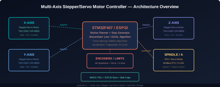
Table of Contents
- 1. Why Build a Custom Motion Controller?
- 2. Hardware Architecture: MCU, Drivers, and Power
- 3. Step Pulse Generation and Timing
- 4. Motion Planning: Trapezoidal vs S-Curve Profiles
- 5. Multi-Axis Coordination: Bresenham and DDAL
- 6. Encoder Feedback and Closed-Loop Control
- 7. G-code Interpreter and Command Buffer
- 8. Driver Selection: TMC2209 vs DRV8825 vs TB6600
- 9. Frequently Asked Questions
1. Why Build a Custom Motion Controller?
Commercial CNC controllers like the GRBL-based Arduino CNC Shield, Smoothieboard, and Duet3D cost $50-$500 depending on features. For simple 3-axis machines, those off-the-shelf solutions work well. But when you need a custom axis configuration — a 4th rotary axis, a specific encoder interface, or coordinated motion with external sensors — building a custom controller gives you complete control over the motion pipeline.
A custom motion controller also eliminates software lock-in. GRBL is limited to 3 axes and lacks acceleration planning beyond basic trapezoidal profiles. Smoothieboard uses a proprietary config format. Building your own controller means you own the firmware, can add any feature you need, and are not dependent on a third-party project’s update schedule.
The STM32F407 is the ideal MCU for custom motion controllers because it has multiple hardware timers that can generate step pulses independently on each axis, a Cortex-M4 core fast enough for real-time acceleration calculations, and enough GPIO for encoders, limit switches, and spindle control.
2. Hardware Architecture: MCU, Drivers, and Power
A multi-axis motion controller requires four functional blocks working together:
Microcontroller: STM32F407VGT6 for best performance, or ESP32 for Wi-Fi/Bluetooth connectivity. The STM32 has 12 hardware timers — assign TIM2-TIM5 for step pulse generation on axes 1-4, and TIM6/TIM7 for the main motion planner tick. The ESP32 lacks hardware timers but uses the MCPWM peripheral for step generation, which works but is less flexible.
Motor Drivers: Each axis needs a dedicated driver board. For stepper motors: TMC2209 (ultra-quiet, stallGuard sensorless homing), DRV8825 (high current, 2.5A), or TB6600 (external module, up to 4.2A). For servo motors: any driver that accepts step/direction input — the servo drive handles the PID control internally.
Power Supply: Stepper motors require high-current 24-48VDC power. A 48V/5A switching supply (Mean Well LRS-200-48) provides enough current for 4 axes at 1.2A each. Add 1000uF electrolytic capacitors on the driver input rails to absorb regenerative current during deceleration. The MCU and logic circuits run on 5V from a buck converter.
Encoders and Limits: AB quadrature encoders on each axis provide position feedback. Use the STM32 hardware encoder interface (available on TIM2-TIM5) for hardware-decoded encoder counts without CPU intervention. Limit switches connect to GPIO with interrupt-on-edge for immediate stop on home or crash detection.
3. Step Pulse Generation and Timing
Step pulse generation is the most time-critical task in a motion controller. Each pulse moves the motor by one microstep. For a motor with 200 steps/revolution and 16x microstepping, that is 3200 pulses per revolution. At 1000 RPM, the step rate is:
Step rate = (RPM x steps_per_rev x microsteps) / 60
Step rate = (1000 x 200 x 16) / 60 = 53,333 pulses/second
The STM32 generates these pulses using Timer Output Compare mode. Configure TIM2 in PWM mode with the timer clock divided to produce the desired step frequency. The timer automatically toggles the output pin at the programmed frequency — no CPU intervention needed. To change speed, simply update the timer’s compare register.
For smooth acceleration, the step frequency must change continuously. The motion planner runs in a Timer Update Interrupt at 1 kHz, calculating the next step frequency based on the acceleration profile. This gives 1000 updates per second — enough for smooth velocity transitions.
4. Motion Planning: Trapezoidal vs S-Curve Profiles
Motor acceleration profiles determine how smoothly the machine transitions between speeds. Two common profiles:
Trapezoidal Profile: Constant acceleration from rest to cruise speed, constant cruise, then constant deceleration to stop. Simple to implement: the planner increments or decrements the step frequency by a fixed amount each tick. Trapezoidal profiles cause jerk (instantaneous acceleration change) at the start and end of each segment, which can cause vibration in rigid machines.
S-Curve Profile: The acceleration itself ramps up and down smoothly, eliminating jerk. The planner uses a cubic or quintic polynomial to compute the step frequency at each tick. S-curve profiles produce smoother motion, reduce mechanical vibration, and allow higher acceleration without resonance. The implementation is more complex — you need to solve a polynomial at each planner tick — but the STM32F407 handles it easily at 1 kHz.
For CNC machines cutting rigid materials (aluminum, steel), S-curve profiles are strongly recommended. The smoother motion produces better surface finish and reduces tool wear. For 3D printers and pick-and-place machines, trapezoidal profiles are sufficient because the loads are lighter and vibration is less critical.
5. Multi-Axis Coordination: Bresenham and DDAL
When a CNC program commands a diagonal move (G1 X10 Y10 F1000), both axes must move simultaneously at coordinated speeds. The Bresenham line algorithm provides this coordination without requiring a floating-point division on each step.
The Bresenham algorithm works by maintaining an error accumulator for each axis. The axis with the longer distance gets the primary step timer. At each timer tick, the primary axis steps and the error accumulator is updated. When the error exceeds the secondary axis distance, the secondary axis also steps and the error is reduced. This produces perfectly coordinated linear motion using only integer addition and comparison.
For 3-axis moves (X+Y+Z), extend Bresenham to three dimensions. For circular interpolation (G2/G3), pre-compute the arc points using integer math (DDA — Digital Differential Analyzer) and feed them to the linear interpolator.
The key optimization: pre-compute the entire motion segment at the start, store the step counts in a ring buffer, and let the timer interrupt consume steps from the buffer. This decouples the G-code parser from the real-time step generation, preventing step misses during complex moves.
6. Encoder Feedback and Closed-Loop Control
Open-loop stepper control assumes the motor never misses a step. In practice, missed steps occur during rapid acceleration, heavy loads, or electrical noise. Encoder feedback provides closed-loop position verification.
The STM32 hardware encoder interface (available on TIM2-TIM5) decodes AB quadrature signals at the timer’s clock rate — up to 16 MHz on the F407. This means you can track encoders with 10,000 CPR (counts per revolution) at 4000 RPM without missing counts.
Implement position error detection by comparing the commanded position (from the step counter) with the actual position (from the encoder). If the error exceeds a threshold (typically 2-3 microsteps), trigger a stop and alarm. This catches missed steps without requiring full PID closed-loop control, which is more complex and typically unnecessary for stepper motors.
For servo motors, the servo drive handles its own PID loop internally. The controller only needs to send the step/direction command and read the encoder position for position verification. Some servo drives (like the Delta ASDA-B2) support EtherCAT or CANopen for more sophisticated closed-loop control.
7. G-code Interpreter and Command Buffer
The G-code interpreter converts text commands into motion segments. A minimal interpreter needs to handle these G-codes:
- G0/G1: Linear move (rapid or feed rate)
- G2/G3: Circular interpolation (CW/CCW arc)
- G28: Home all axes
- G90/G91: Absolute/incremental positioning
- G92: Set position offset
- M3/M5: Spindle on/off
- M8/M9: Coolant on/off
Parse G-code lines into a command structure and store them in a ring buffer. The motion planner consumes commands from the buffer, converting each G1/G2/G3 move into step counts and acceleration profiles. A 256-entry ring buffer provides enough lookahead for smooth motion at moderate feed rates.
For higher performance, implement look-ahead planning: when parsing a new move, examine the next 10-20 moves to calculate junction speeds. This allows the planner to avoid unnecessary deceleration/acceleration cycles at the junction between short moves, significantly improving throughput on complex toolpaths.
8. Driver Selection: TMC2209 vs DRV8825 vs TB6600
Motor driver selection depends on your motor current, noise requirements, and budget:
| Feature | TMC2209 | DRV8825 | TB6600 |
|---|---|---|---|
| Max Current | 2.0A RMS | 2.5A RMS | 4.2A RMS |
| Microstepping | 1/256 | 1/32 | 1/32 |
| Noise Level | Ultra-quiet (StealthChop) | Moderate | Loud at high current |
| StallGuard | Yes (sensorless homing) | No | No |
| Price | $3-5 | $2-3 | $8-12 (module) |
Recommendation: Use TMC2209 for quiet operation and sensorless homing. Use DRV8825 for budget builds where noise is not a concern. Use TB6600 external modules for motors above 2A where TMC2209 cannot deliver sufficient current.
Frequently Asked Questions
Can a custom motion controller replace GRBL?
Yes. A custom controller on STM32F407 can implement all GRBL features (G-code parsing, acceleration planning, step generation) with significantly better performance: 100 kHz+ step rates vs GRBL’s 30 kHz limit, S-curve acceleration vs GRBL’s trapezoidal only, and support for 4+ axes vs GRBL’s 3-axis limit. The trade-off is development time — GRBL works out of the box, while a custom controller requires firmware development.
How many axes can an STM32F407 motion controller support?
With 4 hardware timers dedicated to step generation, the STM32F407 natively supports 4 axes (X, Y, Z, A/B rotary). With software step generation using DMA, you can add a 5th or 6th axis, but at reduced step rates. For 6+ axis applications, consider the STM32F7 or a dual-MCU architecture.
What is the maximum step rate achievable?
Using hardware timer output compare mode, the STM32F407 can generate step pulses at up to 16 MHz (timer clock rate). Practical limit for CNC applications is 100-200 kHz per axis, which supports motors up to 3000 RPM at 1/16 microstepping. Beyond 200 kHz, the driver’s pulse input frequency becomes the limiting factor.
Can I use this controller for 3D printing?
Absolutely. The same architecture works for FDM 3D printers. The key differences: 3D printers typically use NEMA 17 motors (1-2A) which are well within the TMC2209’s range, require heated bed and extruder temperature control (add thermistor inputs and MOSFET outputs), and benefit from TMC2209’s StealthChop mode for silent operation.
How do I handle E-stop in firmware?
Connect the E-stop button to a GPIO pin configured as external interrupt with highest priority. The ISR immediately: (1) disables all timer outputs to stop step pulses, (2) sets all enable pins LOW to de-energize motors, (3) sets the spindle speed to zero, and (4) sets a global flag that prevents motion commands until the E-stop is cleared and the machine is re-homed. This entire sequence completes in under 10 microseconds.
Related Reading
- Stepper Motor Driver Comparison: DRV8825 vs TMC2209
- Stepper Motor Fundamentals: Torque, Speed, and Microstepping
- CNC Calibration Guide: Achieving Accuracy and Positioning
- STM32 vs Arduino for Industrial Applications: Why Professionals Choose STM32
Sources
- Trinamic TMC2209 — SilentStepStick Motor Driver
- Texas Instruments DRV8825 — Stepper Motor Driver
- STMicroelectronics STM32F4 Series
- GRBL — Open Source CNC Motion Controller
- RepRap Wiki — Step Motor Control Theory
Disclosure: This post contains affiliate links. When you purchase through these links, we may earn a small commission at no additional cost to you. This supports our content creation and helps us provide free industrial automation guides.