Key Takeaway: PID control on Arduino transforms open-loop systems into precise closed-loop controllers — keeping temperature within ±0.5°C or positioning a servo motor to sub-degree accuracy using just proportional, integral, and derivative gains tuned with the Ziegler-Nichols method.
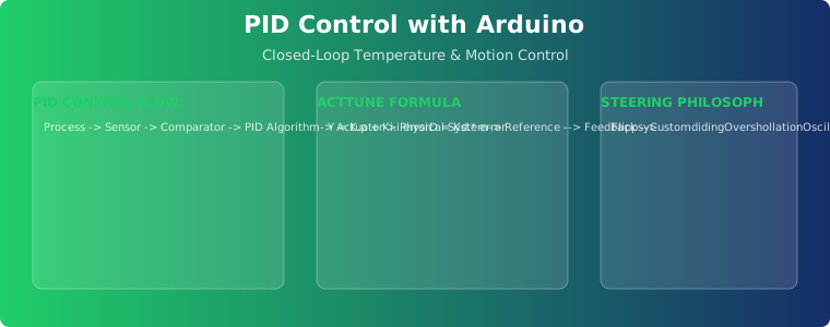
Table of Contents
- 1. What Is PID Control and Why It Matters
- 2. How the PID Algorithm Works
- 3. Implementing PID on Arduino: Step-by-Step
- 4. PID Tuning Methods: Ziegler-Nichols and Auto-Tune
- 5. Practical Example: Closed-Loop Temperature Control
- 6. Practical Example: Servo Motor Position Control
- 7. Common Mistakes and How to Avoid Them
- 8. FAQ
1. What Is PID Control and Why It Matters
Every industrial process — from maintaining oven temperature to positioning a robotic arm — requires keeping a variable at a desired setpoint despite disturbances. PID control (Proportional-Integral-Derivative) is the most widely used feedback control algorithm in industrial automation, appearing in an estimated 95% of all control loops worldwide.
Without PID, you have two bad options: open-loop control (apply fixed power, hope for the best) or simple on/off control (thermostat-style, which oscillates wildly). PID provides smooth, continuous adjustment that reaches the setpoint quickly and holds it稳定.
For Arduino and STM32 embedded systems, PID control is essential for:
- Temperature control: 3D printer hot ends, reflow ovens, industrial furnaces
- Motion control: Servo motor positioning, CNC speed regulation, robotic arm joints
- Flow control: Pump speed regulation, chemical dosing systems
- Pressure control: Pneumatic systems, hydraulic actuators
2. How the PID Algorithm Works
The PID algorithm calculates a control output by combining three terms:
output = Kp × error + Ki × integral(error) + Kd × derivative(error)

where:
  error = setpoint - measured_value
  integral(error) = sum of all past errors × time_step
  derivative(error) = (current_error - previous_error) / time_step
Proportional (P): Reacts to the current error. The larger the gap between setpoint and measured value, the stronger the correction. P alone produces steady-state error — it never quite reaches the setpoint because some error is needed to generate a non-zero output.
Integral (I): Accumulates past errors over time. Even a small persistent error grows the integral term until it drives the output enough to eliminate the offset. The downside: too much integral action causes overshoot and oscillation (integral windup).
Derivative (D): Predicts future error based on its rate of change. If the error is decreasing rapidly (approaching setpoint), D reduces the output to prevent overshoot. If the error is increasing rapidly (disturbance), D increases the output to resist the change.
3. Implementing PID on Arduino: Step-by-Step
The most reliable approach is using the PID library by Brett Beauregard (Arduino PID Library v1.2.1), which includes anti-windup, output clamping, and directional control. Here is a complete implementation:
#include <PID_v1.h>

// Sensor: LM35 temperature sensor on A0
// Actuator: MOSFET driving a 12V heater on pin 3

double Setpoint = 60.0;  // Target: 60°C
double Input, Output;

// PID tuning parameters (initial values)
double Kp = 2.0, Ki = 0.5, Kd = 1.0;

PID myPID(&Input, &Output, &Setpoint, Kp, Ki, Kd, DIRECT);

void setup() {
    Serial.begin(115200);
    myPID.SetMode(AUTOMATIC);
    myPID.SetOutputLimits(0, 255);     // PWM range
    myPID.SetSampleTime(100);          // 100 ms cycle
    pinMode(3, OUTPUT);
}

void loop() {
    // Read temperature
    int raw = analogRead(A0);
    Input = (raw / 1024.0) * 500.0;   // LM35: 10mV/°C

    // Compute PID
    myPID.Compute();

    // Apply output to heater
    analogWrite(3, (int)Output);

    // Log for tuning
    Serial.print("SP:"); Serial.print(Setpoint);
    Serial.print(" PV:"); Serial.print(Input);
    Serial.print(" OUT:"); Serial.println(Output);

    delay(100);
}
The library handles the critical implementation details: derivative-on-measurement (not derivative-on-error, which causes setpoint kick), proportional-on-measurement (optional anti-windup), and integral anti-windup clamping.
4. PID Tuning Methods: Ziegler-Nichols and Auto-Tune
Manual Tuning (Ziegler-Nichols Closed-Loop Method)
- Set Ki = 0 and Kd = 0
- Slowly increase Kp until the system oscillates continuously at constant amplitude
- Record this as Ku (ultimate gain) and Tu (oscillation period)
- Calculate PID parameters: Kp = 0.6×Ku, Ki = 2×Kp/Tu, Kd = Kp×Tu/8
This method provides a good starting point, but industrial applications typically require fine-tuning by 20–40% from the calculated values.
Arduino Auto-Tune
The PID library includes a built-in auto-tune mode using relay feedback. Enable it with:
myPID.SetMode(AUTOMATIC);
// Use PIDRelay library or manual relay method:
// 1. Output toggles between 0 and a fixed value
// 2. System oscillates around setpoint
// 3. Library measures oscillation period and amplitude
// 4. Calculates Kp, Ki, Kd automatically
For production systems, auto-tune is preferred because it adapts to the actual system dynamics — including nonlinearities, dead time, and thermal lag that manual calculation cannot predict.
5. Practical Example: Closed-Loop Temperature Control
A reflow oven PID controller using Arduino Uno, MAX6675 thermocouple module, and a solid-state relay (SSR) driving a 1500W heating element:
// Reflow soldering profile: ramp → soak → reflow → cool
// Target peak: 245°C with ±3°C tolerance

struct ReflowProfile {
    float soak_temp;     // 150°C
    float soak_time;     // 90 seconds
    float reflow_temp;   // 245°C
    float reflow_time;   // 30 seconds
};

double Kp = 150.0;   // High Kp for fast ramp
double Ki = 0.5;     // Low Ki to prevent overshoot
double Kd = 500.0;   // High Kd to brake before peak
For reflow soldering, the derivative term is critical — it “sees” the rapid temperature rise and reduces output before the target is reached, preventing thermal overshoot that could damage components. The Kd value is typically 3–5× higher than Kp for this application.
6. Practical Example: Servo Motor Position Control
PID position control for a servo motor with encoder feedback. The key difference from temperature control: response speed must be much faster (1 kHz PID loop vs 10 Hz for temperature).
// Servo PID parameters
double Kp = 8.0;    // Position gain
double Ki = 0.05;    // Very small — eliminates steady-state error
double Kd = 2.5;     // Dampens oscillation at target

// 1 kHz PID loop using Timer1 interrupt
ISR(TIMER1_COMPA_vect) {
    int32_t position = readEncoder();
    double error = target_position - position;

    // Calculate PID
    integral += error * 0.001;  // dt = 1ms
    double derivative = (error - last_error) / 0.001;

    output = Kp * error + Ki * integral + Kd * derivative;
    last_error = error;

    // Apply to motor driver (PWM + direction)
    setMotorOutput(output);
}
For motion control, limit the integral term to prevent windup during large setpoint changes (anti-windup clamp at ±50% of max output). Use derivative filtering (low-pass filter on D term) to prevent high-frequency noise from causing jitter.
7. Common Mistakes and How to Avoid Them
Mistake 1: Derivative kick. When the setpoint changes suddenly, the error derivative spikes, causing a violent output change. Solution: compute derivative on the measured value, not the error. The PID library does this by default.
Mistake 2: Integral windup. When the output is saturated (e.g., heater at 100% PWM) and the error persists, the integral term grows unbounded. When conditions change, it takes a long time to unwind. Solution: Implement integral clamping — limit the integral sum to the output range.
Mistake 3: Sampling too slowly. A PID controller must sample at least 10× faster than the system’s response time. For a temperature system with a 30-second time constant, sample every 3 seconds maximum. For motor control with a 10 ms time constant, sample every 1 ms.
Mistake 4: Ignoring noise. Sensor noise directly affects the derivative term, causing erratic output. Solution: average multiple readings (moving average filter) or implement a low-pass filter on the D term: D_filtered = D_raw × alpha + D_filtered × (1-alpha) with alpha = 0.1–0.3.
Frequently Asked Questions
Can Arduino handle PID control for industrial applications?
Arduino Uno handles single-loop PID well (10–100 Hz update rate). For multi-axis control or loops faster than 1 kHz, upgrade to Arduino Mega 2560 or STM32. For safety-critical applications requiring certified controllers, use Arduino as a prototype platform and migrate the validated PID algorithm to a commercial PLC or dedicated motion controller.
How do I know if my PID is properly tuned?
A well-tuned PID system shows: (1) fast response to setpoint changes (rise time), (2) minimal overshoot (less than 10%), (3) quick settling to within ±2% of setpoint, and (4) rejection of disturbances within 1–2 time constants. Use Serial Plotter to visualize the response curve.
What is the difference between PID and PI control?
PI control (without derivative) is simpler and works well for slow systems like temperature regulation where overshoot is tolerable. PID adds the derivative term for faster systems where overshoot prevention is critical — motor positioning, robotics, and real-time pressure control. Many temperature systems use PI control and achieve excellent results.
How often should I update the PID loop?
The PID update rate should match the system dynamics: temperature control at 1–10 Hz (100–1000 ms), motor position control at 100–1000 Hz (1–10 ms), and high-speed servo control at 1–10 kHz (0.1–1 ms). Always use a fixed time step — variable dt causes integral and derivative errors.
Can I use PID for both heating and cooling?
Yes, but you need a bidirectional output. Use PID with reverse acting for heating (output increases when temperature is below setpoint) and direct acting for cooling. In industrial systems, a single PID loop controlling both a heater and a cooling fan uses two PWM outputs driven by the same PID calculation with output deadband.
Related Reading
- Arduino Servo Motor Control: Complete Library and PWM Guide
- STM32 PWM Signal Generation for Motor Speed Control
- Closed-Loop vs Open-Loop Stepper Motors: Which Is Best for CNC?
- Multi-Axis Stepper Servo Motor Controller Design for CNC and Robotics
Sources
- Wikipedia — PID Controller
- Arduino PID Library by Brett Beauregard
- Ziegler-Nichols PID Tuning Method
- Caltech — PID Control Tutorial
- Omega Engineering — PID Controller Tuning Guide
Disclosure: This post contains affiliate links to recommended Arduino boards, sensors, and motor drivers. If you purchase through these links, we may earn a commission at no extra cost to you.