

Key Takeaway: A PID controller turns a motor into a precision motion device by continuously comparing the actual speed or position with the target and adjusting the PWM output using three terms — proportional, integral, and derivative — and with the right tuning procedure you can implement closed-loop control on an Arduino or STM32 in under an hour.
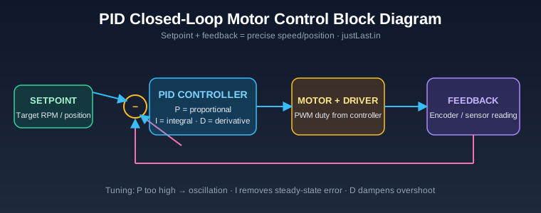
Table of Contents
1. What PID Control Actually Does
An open-loop motor spins when you give it power, but it has no idea how fast it is going. Load the shaft, the speed drops; the supply sags, the speed drops again. For a workshop build — a spindle, a conveyor, an XY stage — open-loop speed control is often not good enough. PID motor control solves this by closing the loop: a sensor measures the actual motor speed or position, the controller computes the error against the target, and it adjusts the PWM output to drive that error to zero.
The loop runs fast and continuously — typically every 1 to 20 milliseconds. Each iteration the controller reads feedback, calculates the error, runs the PID math, and writes a new PWM duty cycle. This is the same control structure that stepper-servo systems use internally, and it is the reason a servo holds its position while a plain stepper cannot; our stepper vs servo comparison explains why that feedback matters on a CNC machine.
2. The Three Terms: P, I, and D
A PID controller combines three calculations, each correcting a different type of error:
- Proportional (P): Output is proportional to the current error. A big error produces a big correction. P alone always leaves a steady-state error, because a small error produces too little output to overcome friction or load.
- Integral (I): Output grows with the accumulated error over time. The integral term is what eliminates steady-state error — it keeps pushing until the error is truly zero. Too much I causes overshoot and slow oscillation.
- Derivative (D): Output responds to the rate of change of the error. D acts like a brake on the response, damping overshoot and settling the system faster. Too much D amplifies sensor noise.
Each term has a gain — Kp, Ki, Kd — and tuning means finding the three values that give fast response without oscillation. The full formula is: output = Kp·e + Ki·∫e·dt + Kd·(de/dt), where e is the error.
3. Hardware You Need
For a DC motor speed-control experiment you need four things:
- A DC motor (any geared 6-12 V motor works).
- An encoder on the motor shaft — either a hall-effect encoder wheel with an LM393 sensor, or a built-in quadrature encoder if your motor has one.
- A motor driver capable of PWM input — an L298N, L293D, or better a TB6612, DRV8833, or a discrete H-bridge MOSFET driver.
- A microcontroller — an Arduino Uno/Nano or an STM32 board such as the Blue Pill.
For position control you also need the encoder count to be meaningful; use a wheel with 20-40 slots or a 400 PPR quadrature encoder for smooth readings. The hardware approach is identical to the wiring in our stepper motor driver guide, except now the feedback pin matters as much as the drive pins.
4. PID Motor Control with Arduino: Code
Here is a complete Arduino sketch for PID motor control Arduino-style closed-loop speed control using an interrupt-driven encoder:
#include <PID_v1.h>

const int ENC_A = 2;   // encoder channel A (interrupt pin)
const int ENC_B = 3;   // encoder channel B
const int PWM = 9;     // motor driver PWM pin
const int IN1 = 7;     // motor direction
const int IN2 = 8;

volatile long encoderCount = 0;
double setpoint = 1500;   // target RPM
double input = 0, output = 0;
double Kp = 2.0, Ki = 0.5, Kd = 0.05;

PID myPID(&input, &output, &setpoint, Kp, Ki, Kd, DIRECT);
unsigned long lastRead = 0;

void setup() {
  pinMode(PWM, OUTPUT);
  pinMode(IN1, OUTPUT);
  pinMode(IN2, OUTPUT);
  attachInterrupt(digitalPinToInterrupt(ENC_A), encoderISR, CHANGE);
  myPID.SetMode(AUTOMATIC);
  myPID.SetOutputLimits(0, 255);
  myPID.SetSampleTime(10);
}

void loop() {
  unsigned long now = millis();
  if (now - lastRead >= 100) {
    input = (double)encoderCount * 60.0 / 40.0; // RPM with 40 counts/rev
    encoderCount = 0;
    lastRead = now;
  }
  myPID.Compute();
  analogWrite(PWM, (int)output);
  digitalWrite(IN1, HIGH);
  digitalWrite(IN2, LOW);
}

void encoderISR() {
  if (digitalRead(ENC_B)) encoderCount++;
  else encoderCount--;
}
The sketch reads the encoder twice per revolution edge, converts counts into RPM every 100 ms, runs the PID computation, and writes the result to the PWM pin. The PID library handles the P, I, and D math internally; your job is only to supply feedback and apply the output. Start with these gains and tune from there.
5. Implementing PID on STM32
On an STM32 the approach is identical but you gain much higher loop rates and a hardware timer for the encoder. Use TIM1/TIM2 as a quadrature encoder interface (encoder mode), which counts pulses in hardware without interrupts, and use a timer PWM channel for the output. The PID function itself is a small fixed-point or float routine called from the timer interrupt at 1-5 kHz.
Because STM32 runs at 72-168 MHz, you can sample the encoder every millisecond instead of every 100 ms, which lets you run much higher Kp and Kd values without oscillation — the machine simply reacts faster. For a production conveyor or spindle controller, that responsiveness is exactly what makes an STM32 worth choosing over an 8-bit Arduino; our STM32 vs Arduino comparison covers the platform trade-offs in depth.
A minimal STM32 HAL approach: configure the encoder timer, read TIM->CNT as position, compute error and PID in a 1 ms timer callback, and update the PWM compare register. The same PID gains transfer from the Arduino test rig as a starting point, though you will typically raise Kp by 3-5× because of the faster loop.
6. Tuning: From Oscillation to Stability
Tuning is the part everyone struggles with, but a systematic procedure makes it simple:
- Set Ki and Kd to zero.
- Increase Kp until the motor oscillates (speed swings around the target).
- Back Kp off to about half of the oscillation value.
- Increase Ki slowly until the steady-state error disappears.
- Add Kd a little at a time until overshoot stops, testing after each change.
This is the classic Ziegler-Nichols approach adapted for trial and error. Watch the behaviour: too much P gives fast, buzzing oscillation; too much I gives slow, lazy oscillation; too much D makes the motor twitchy and noisy. A well-tuned system reaches the target quickly with no more than one small overshoot and settles in under half a second for a small motor.
Remember that gains are not transferable between machines. A big industrial servo drive needs completely different gains than a small bench motor — the inertia is different. The tuning loop is the same skill that our stepper vs servo guide mentions when it warns that servo systems must be tuned per machine.
7. Common Mistakes and Fixes
- Feedback sign flipped: the motor runs away instead of stabilising. Swap the encoder channel pins or the motor polarity.
- Duty cycle wraps: always clamp the PID output to the PWM range with SetOutputLimits, or the motor runs at full speed permanently.
- Sample time too slow: if the loop runs slower than the motor’s mechanical time constant, the control becomes unstable. Run the PID at 10 ms or faster.
- Encoder noise: use pull-up resistors and short twisted wires; derivative term amplifies noise into jitter.
- Integral windup: when the output is clamped, stop accumulating the integral term, or you get a large overshoot when the error finally shrinks.
Frequently Asked Questions
What is PID control in a motor?
PID control is a closed-loop method where a controller reads the motor’s actual speed or position from a sensor, compares it with the target, and adjusts the PWM output using proportional, integral, and derivative terms to minimise the error continuously.
Can I run PID motor control on an Arduino Uno?
Yes. An Arduino Uno easily handles a 10 ms PID loop with an interrupt-driven encoder. For faster loop rates or position control with high-resolution encoders, an STM32 gives you hardware encoder counters and much higher sampling rates.
How do I choose Kp, Ki, and Kd values?
Start with Ki and Kd at zero, raise Kp until the system oscillates, halve it, then add Ki to remove steady-state error and Kd to damp overshoot. Test after every change with the motor under a realistic load.
Why does my PID motor speed oscillate?
Oscillation usually means too much proportional gain or too much integral action. Reduce Kp first; if the oscillation is slow and sinusoidal, reduce Ki. A small amount of Kd can also damp the response.
What encoder should I use for motor speed feedback?
A hall-effect wheel encoder with 20-40 slots or a quadrature encoder with 200-400 PPR is ideal for speed control. For position control, use a higher-resolution quadrature encoder with an interrupt- or timer-based counter.
Related Reading
- Stepper Motor Control with DRV8825 Driver and Arduino
- Stepper vs Servo Motors for CNC: Complete Selection Guide
- STM32 vs Arduino: Which Platform Is Right for Industrial Automation?
- STM32 I2C Communication Masterclass
Sources
- Wikipedia — PID Controller
- Brett Beauregard — Improving the Beginner’s PID
- Analog Devices — PID Control Technical Article
- Texas Instruments — PID Implementation in Microcontrollers
Disclosure: This post contains affiliate links. If you purchase through them, justLast.in may earn a small commission at no extra cost to you. Pick up an Arduino board and motor encoder kits on Amazon.in.


