Industrial Motion Control: Complete Guide to Servo, Stepper and Axis Design
Key Takeaway
Motion control is three layers: command (profile), control loops (position, velocity, current), and drives (servo, stepper, VFD). Match the motor and drive to the load inertia, tune the loops inside out, and size the mechanics for the bandwidth.
Figure 1: Industrial motion control stack – command, control loops, drives, mechanics
Table of Contents
1. Command Layer: Profile and Trajectory
Motion profile
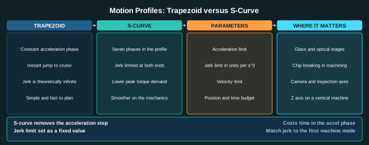
The motion profile defines how the axis moves from point A to point B: acceleration, cruise speed, deceleration, and dwell. The two common profiles are trapezoidal (constant acceleration) and S-curve (jerk-limited). S-curve reduces mechanical ring and settling time at the cost of longer move time.
Trajectory planner
The trajectory planner converts the target position into a sequence of position, velocity and acceleration setpoints. It runs in the controller (PLC, IPC or motion controller) and outputs setpoints to the servo drive at the position loop rate (1 to 10 ms).
Interpolation
For multi-axis moves (linear interpolation, circular interpolation), the planner computes coordinated positions for all axes so they arrive together. CNC machining and pick-and-place robots use interpolation heavily.
2. Control Loops: Current, Velocity, Position
The three nested loops
A servo axis has three nested loops, each inside the other:
- Current loop (50 to 100 us): controls motor current, which is proportional to torque.
- Velocity loop (250 us): controls motor speed by commanding current.
- Position loop (1 to 10 ms): controls motor position by commanding velocity.
Each loop must be 5 to 10 times slower than the one inside it. Tune inside out: current first, then velocity, then position.
Current loop
The current loop reads motor current from shunt resistors and commands PWM to match. Its output is torque. Tuned at the factory; verify motor parameters match the nameplate.
Velocity loop
The velocity loop reads encoder velocity and commands current. P gain sets stiffness; I gain removes steady-state droop. Bandwidth 250 us.
Position loop
The position loop reads encoder position and commands velocity. P gain sets how aggressively it follows position error. Bandwidth 1 to 10 ms.
3. Drives: Servo, Stepper and VFD
Servo amplifier
A servo amplifier drives a brushless servo motor with closed-loop position control. High performance, high cost, used for precision axes, robotics and CNC.
Stepper driver
A stepper driver drives a stepper motor in open loop (no encoder feedback typically). Lower cost, lower performance, used for simple positioning, conveyor indexing and low-cost axes.
VFD for spindles
A VFD (variable frequency drive) drives an induction or PM spindle motor. Used for spindle speed control in CNC machines, not for precise positioning.
Braking and regen
During deceleration, the motor acts as a generator and pumps energy into the drive DC bus. A regeneration resistor (brake resistor) dissipates this energy to prevent overvoltage faults.
4. Mechanics: Gearbox, Screw and Frame
Gearbox or coupling
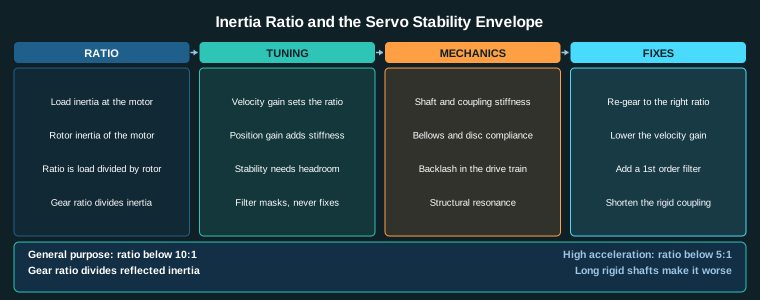
The gearbox reduces motor speed and multiplies torque. It also divides reflected load inertia by ratio squared, making tuning easier. A 10:1 gearbox divides load inertia by 100 at the motor.
Ball screw or linear rail
The screw converts rotary motion to linear motion. Ball screws are precise and efficient; lead screws are cheaper but less precise. Linear rails guide the carriage and carry the load.
Guideway and ways
Linear guideways (profile rails, round ways) support and guide the moving carriage. They are wear items rated in kilometers of travel.
Machine frame
The frame supports everything. Frame stiffness sets the machine’s natural frequency, which limits the achievable position loop bandwidth. A flexible frame limits performance regardless of the drive.
5. Axis Selection Procedure
Step-by-step
- Determine load.Force, speed, accuracy, duty cycle.
- Select motor type.Servo for precision and dynamics; stepper for low-cost positioning; VFD for spindles.
- Select gear ratio.Balance motor speed against load speed; reduce reflected inertia.
- Size drive.Continuous and peak current for the motor; regeneration for deceleration.
- Select mechanics.Screw, coupling, guideway, frame for stiffness and life.
- Tune loops.Current, velocity, position, inside out.
Selection criteria
- Inertia ratio.Below 10:1 general, below 5:1 high acceleration.
- Bandwidth.Position loop 5 to 10 times slower than velocity loop; velocity loop 5 to 10 times slower than current loop.
- Frame stiffness.Frame natural frequency above the position loop bandwidth.
Related Reading
- Servo Tuning: Position, Velocity and Current Loops Explained
- Inertia Ratio and Servo Oscillation: Causes, Limits and Fixes
- Shaft Couplings for Machine Axes: Rigid, Flexible and Backlash-Free
- Servo Drive Selection and Sizing: Power, Regeneration and Cable
Sources
- Yaskawa, Motion Control and Servo Systems
- Rockwell Automation, Kinetix Motion Control
- Siemens, SINAMICS and SIMOTION Motion Control
- IEC 61800-5-1, Adjustable speed electrical power drive systems: Safety requirements
Key Takeaways
- Motion control is three layers: command (profile), control loops (current, velocity, position), and mechanics (drive train, frame).
- Tune loops inside out: current first, velocity second, position third.
- Each loop must be 5 to 10 times slower than the one inside it.
- Inertia ratio below 10:1 for general axes, below 5:1 for high-acceleration axes.
- Frame stiffness sets the achievable position loop bandwidth; a flexible frame limits performance regardless of the drive.