Shaft Couplings for Machine Axes: Rigid, Flexible and Backlash-Free
Key Takeaway
Rigid coupling backlash free couplings such as bellows and servo disc couplings give zero backlash and high torsional stiffness but only absorb about 0.1 mm of parallel misalignment. An elastomer spider coupling absorbs misalignment well but inserts a low frequency torsional mode that the position loop can excite and hunt on.
Figure 1: Shaft couplings selection – rigid, flexible, and backlash-free types
Table of Contents
- 1. What a Coupling Has to Do
- 2. Bellows Couplings: The Default for a Rigid Axis
- 3. Jaw and Disc Couplings: The Alternatives
- 4. Elastomer Spider Couplings: Forgiving and Unforgiving
- 5. Torsional Stiffness and the Resonant Mode
- 6. Alignment and the Runout Budget
- 7. Rigid Coupling Backlash Free Selection: Cost and the Purchasing Decision
- Related Reading
- Sources
1. What a Coupling Has to Do
The coupling between the motor and the load is the cheapest component in the drive train and the one most often chosen by habit rather than by calculation. It does three jobs at once and they pull against each other. Rigid coupling backlash free selection is an exercise in matching the alignment tolerance you will actually have to the torsional stiffness you actually need.
| Job | What it needs | What it costs |
|---|---|---|
| Transmit torque | High torsional stiffness | A stiff coupling transmits misalignment to the bearings |
| Absorb misalignment | Compliance | Compliance is a low-frequency torsional mode |
| Protect the drive | Shock absorption, overload limiting | An elastomer coupling is the one that does this, and it has backlash |
You cannot have all three at once. Rigid coupling backlash free selection is the process of deciding which one you are giving up, and the honest way to do it is to work out how much misalignment the machine will actually have before choosing the type.
The four alignments
- Parallel misalignment is the two shafts being offset sideways. The coupling has to absorb it.
- Angular misalignment is the two shaft axes being tilted relative to each other. Also absorbed by the coupling.
- Axial displacement is the shafts moving towards or away from each other as the machine warms up.
- Radial runout is the shaft not being perfectly straight or not being centred on the bearing. The coupling cannot fix this, but it can amplify it into a cyclic position error.
2. Bellows Couplings: The Default for a Rigid Axis
Rigid coupling backlash free selection is an exercise in matching the alignment tolerance you will actually have to the torsional stiffness you actually need. The bellows coupling is the default for a rigid coupling backlash free requirement, because it is the cheapest way to get both zero backlash and high stiffness.
How it works
The bellows coupling is the default for a rigid coupling backlash free requirement, because it is the cheapest way to get both zero backlash and high stiffness. Two thin-walled stainless steel or nickel alloy bellows are welded to either side of a spacer, and the bellows are machined from solid so that the wall thickness is uniform. There is nothing to wear, nothing to lubricate and nothing that can introduce backlash, because there is no clearance between the driving and the driven member.
The numbers
| Property | Bellows coupling, 30 to 90 mm |
|---|---|
| Backlash | Effectively zero, under 0.1 arcmin |
| Torsional stiffness | 3,000 to 30,000 Nm per radian depending on size |
| Parallel misalignment | 0.1 to 0.5 mm |
| Angular misalignment | 0.5 to 2 degrees |
| Axial displacement | 1 to 3 mm |
| Maximum speed | Up to 30,000 rpm |
| Peak torque | 2 to 4 times rated |
The stiffness and the position error
Stiffness matters because the coupling is in the control loop. A coupling of 5,000 Nm per radian carrying 10 Nm of torque deflects by:
theta = T / k = 10 / 5000 = 0.002 rad = 0.115 degrees
At a 200 mm effective radius, that is an angular displacement of the load relative to the motor of 0.002 x 0.200 = 0.4 mm. The servo closes the loop on the motor, so the drive thinks the load is exactly where the motor is, and the 0.4 mm twist is invisible to the controller. It shows up as a position error that varies with load, and it does not show up in any repeatability measurement taken at one load.
Double the stiffness to 10,000 Nm per radian and the twist halves to 0.2 mm. That is the argument for the stiffest coupling the machine can actually align.
Where bellows couplings are the wrong answer
- Shock loads.A bellows coupling transmits a shock straight into the motor bearings. If the drive train can jam, use a coupling with a torque limiter or an elastomer element.
- Large misalignment.0.1 mm parallel is tight. A machine assembled on a shop floor with a flexible mounting plate can easily be 0.2 mm out, and the coupling will be working at its limit from day one.
- Very low torque with high stiffness.The geometry of a bellows is fixed, so a small coupling for a small torque is relatively less stiff.
3. Jaw and Disc Couplings: The Alternatives
Jaw coupling with an elastomer spider
The jaw and disc types are the alternatives in rigid coupling backlash free selection, and they differ in how they take up misalignment. A jaw coupling has two hubs with interlocking jaws, with an elastomer spider or a pin bush between them. The elastomer provides the compliance. It is a good coupling when the alignment is poor, because it absorbs 0.3 to 0.5 mm of parallel misalignment and up to 5 degrees of angular misalignment without complaint.
The price is a torsional stiffness of 300 to 2,000 Nm per radian, which is 5 to 15 times softer than a bellows coupling of the same size. And it has backlash of 1 to 5 arcminutes, because the elastomer has to be compressed for the jaws to engage. That backlash is taken up under load, so on a positioning axis it produces a position error at every direction reversal of 0.02 to 0.1 mm on a 200 mm radius.
Disc coupling
A disc coupling has two thin discs separated by a diaphragm or a Belleville spring stack, or a disc pack with an elastomer. The diaphragm version is very stiff and backlash free, with a stiffness of 10,000 to 100,000 Nm per radian and parallel misalignment of about 0.1 mm. It also has a natural frequency well above any control bandwidth, which makes it the choice for very high speed applications.
Oldham coupling
For two parallel shafts that must accommodate angular misalignment in two planes, the Oldham coupling is the answer. It uses two discs with ten lips that slide on each other, and it is backlash free and extremely rigid in torsion while allowing parallel and angular misalignment at the same time. It is the standard choice for optical benches and for the gantry axes of a laser cutting machine.
Grid coupling
A grid coupling uses a flexible metal grid that flexes as it transmits torque. It handles shock well, absorbs significant misalignment, and has very high torsional stiffness because the grid is metal. Its weakness is that it has real backlash and it needs lubrication, which makes it unsuitable for a clean room and for any axis that must hold position precisely.
4. Elastomer Spider Couplings: Forgiving and Unforgiving
The torsional mode
The elastomer spider is the forgiving choice, and it is exactly that for rigid coupling backlash free work: forgiving in alignment, unforgiving in stiffness. This is the reason the spider coupling causes hunting on a stiff axis, and it is worth understanding rather than memorising.
An elastomer spider coupling is a torsion spring with a stiffness of, say, 800 Nm per radian. It connects two inertias. The mode frequency of that two-mass system is:
Take a 750 W motor with J1 = 0.31e-4 kg m^2 and a load of J2 = 3.27e-3 kg m^2 (the machine axis from the inertia ratio guide), with k = 800 Nm per radian:
f_res = 0.1592 x sqrt( 800 x (32258 + 306) ) = 0.1592 x sqrt( 800 x 32564 ) = 0.1592 x sqrt(2.605e7) = 0.1592 x 5104 = 813 Hz
f_res = 0.1592 x sqrt( 800 x (32258 + 306) ) = 0.1592 x sqrt( 800 x 32564 ) = 0.1592 x 5104 = 813 Hz
813 Hz is far above the position loop bandwidth, so this coupling is fine. Now the same coupling on a lighter load of 5e-4 kg m^2:
f_res = 0.1592 x sqrt( 800 x (32258 + 2000) ) = 0.1592 x sqrt( 800 x 34258 ) = 0.1592 x sqrt(2.741e7) = 0.1592 x 5235 = 833 Hz
Still high. A spider coupling only becomes a problem when the load inertia is large, which pushes the mode down. With J2 = 0.05 kg m^2 and the same k:
f_res = 0.1592 x sqrt( 800 x (32258 + 20) ) = 0.1592 x sqrt( 800 x 32278 ) = 0.1592 x sqrt(2.582e7) = 0.1592 x 5082 = 809 Hz
Hmm, that is still high. The reason is that the motor inertia is small and the load inertia term dominates only when the load is small. Let me reconsider: the mode drops when the load inertia is LARGE, because 1/J2 becomes small and 1/J1 dominates. The formula sqrt(k x (1/J1 + 1/J2)) – with a large J2, 1/J2 -> 0, and the mode becomes sqrt(k/J1)/(2 pi). With k = 800 and J1 = 0.31e-4: f = 0.1592 x sqrt(800 / 0.31e-4) = 0.1592 x sqrt(2.58e6) = 0.1592 x 1606 = 256 Hz.
256 Hz is still above the position loop bandwidth but it is inside the range where a fast position loop can start to interact with it, and with a stiffer coupling it comes down further. With k = 5,000: f = 0.1592 x sqrt(5000 / 0.31e-4) = 0.1592 x sqrt(1.613e7) = 0.1592 x 4016 = 639 Hz. With k = 50,000: f = 0.1592 x 12,700 = 2,022 Hz.
The practical conclusion: an elastomer spider coupling on a machine with a heavy load is not the cause of the hunting by itself, but it removes the stiffness that the position loop was relying on, and the loop has to be re-tuned with it in place. A coupling swapped for a more flexible type is a genuine cause of a hunting axis appearing overnight after a maintenance job.
When it is the right answer
- Shock and vibration are the concern, such as a press or a reciprocating load.
- Alignment is poor and will stay poor, such as on a retrofit with an old cast iron bed.
- The load is a conveyor or a mixer and backlash does not matter.
- The coupling must absorb the thermal growth of a long shaft between the motor and the load.
5. Torsional Stiffness and the Resonant Mode
Why it matters
Torsional stiffness is the number that connects rigid coupling backlash free selection to the tuning of the axis. The stiffness sets two things: the position error under load, and the frequency of the torsional mode. Both matter and they pull in opposite directions, which is why the coupling choice is a real trade rather than a lookup.
Position error under load
As computed in section 2, a coupling of 5,000 Nm per radian at 10 Nm of torque deflects by 0.002 rad, which is 0.11 degrees and about 0.38 mm at a 200 mm radius. If the load varies, so does the position. On a machine where the load varies with the cut, that variation is a real and repeatable position error that no amount of servo tuning removes, because the drive is closing the loop on the motor.
The stiffness needed for a given error budget: theta_max = T / k, so k >= T / theta_max. For a 0.05 mm error at 200 mm radius with 10 Nm of varying torque, theta_max = 0.00005 / 0.200 = 2.5e-4 rad, and k >= 10 / 2.5e-4 = 40,000 Nm per radian. That is in disc coupling territory, not bellows territory.
The resonant mode
The mode frequency is f_res = (1 / 2 pi) x sqrt(k x (1/J1 + 1/J2)). As the stiffness goes up, the mode goes up, which is good: it moves away from the position loop bandwidth. So the stiffness and the mode frequency both improve together, and the only cost of a stiff coupling is that it will not tolerate misalignment.
| Coupling type | Stiffness (Nm/rad) | Mode with J1 = 0.31e-4, J2 = 3.27e-3 | Mode with J2 = 0.05 |
|---|---|---|---|
| Spider elastomer, 800 Nm/rad | 800 | 813 Hz | 809 Hz |
| Bellows, 5,000 Nm/rad | 5,000 | 2,028 Hz | 2,022 Hz |
| Bellows, 15,000 Nm/rad | 15,000 | 3,511 Hz | 3,506 Hz |
| Disc with diaphragm, 40,000 Nm/rad | 40,000 | 5,699 Hz | 5,691 Hz |
All of these are above the position loop bandwidth, so the mode is not directly excited by the loop. The problem with a compliant coupling is not the mode itself but the reduced stiffness available to the loop, which forces the velocity and position gains down.
The selection criteria, in order
- Torque and peak torque.Rated torque above the working torque with at least a 2x margin on peak.
- Stiffness against the error budget.Calculate the twist under the varying load and check it against the position tolerance.
- Alignment against the machine’s actual build accuracy.This is the number that rules couplings out.
- Speed and balance.Couplings above 3000 rpm need a balance class of G6.3 or better.
- Backlash against the positioning requirement.Zero for anything below 0.05 mm.
- Environment.Clean room, food grade, oil resistance, temperature.
6. Alignment and the Runout Budget
Total indicated runout
The alignment tolerance of the coupling and the runout of the shafts have to be budgeted together, and that is where rigid coupling backlash free selection actually bites. Total indicated runout, or TIR, is the total variation in the runout of a shaft as it rotates. A new servo motor shaft typically has 0.005 to 0.02 mm of TIR. The coupling adds its own runout, typically 0.01 to 0.05 mm.
The important consequence: runout appears as a cyclic position error at the load, once per motor revolution. At a 200 mm effective radius and 0.02 mm of total runout at the motor, the position error at the load is 0.02 x 200 / 100 = 0.04 mm, repeating every revolution. On a precision axis that is a large fraction of the total error budget, and it is invisible in a repeatability measurement taken at one position.
Runout also causes a once-per-revolution vibration, which shows up as a buzz on the axis and as a periodic force at the bearings. On a machine with a linear scale the runout at the motor is not measured at all, because the scale closes the loop at the load, so the runout stops affecting the position but the mechanical vibration remains.
The alignment budget
The total error at the load from misalignment is the sum of the contributions, and they add approximately in quadrature because they are at different angles and different frequencies:
| Source | Contribution at 200 mm radius |
|---|---|
| Coupling runout, 0.03 mm | 0.06 mm |
| Motor shaft runout, 0.015 mm | 0.03 mm |
| Parallel misalignment, 0.1 mm | 0.1 mm at the coupling, foreshortened at the load |
| Angular misalignment, 1 degree | 0.1 mm at the coupling |
How to achieve the alignment
- Shim at the motor feet.Most of the alignment is done here. A dial indicator on the coupling hub, rotated through one revolution, shows the angular and parallel error at the motor and the shims correct it.
- Do not use the coupling as an alignment device.A flexible coupling hides misalignment; it does not correct it. A bellows coupling running at 0.2 mm parallel offset is at its limit and will fail early.
- Re-check after the motor is torqued.The alignment changes when the motor bolts are tightened, because the housing deforms. Align, tighten, then re-check.
- Re-check after a month.Cast iron beds move as they warm up and as the machine settles. An alignment that was perfect at commissioning is often 0.05 mm out after a month of running.
- Record it.Write the TIR and the alignment figures on the machine’s acceptance sheet. When a coupling fails a year later, the figures tell you whether it was the alignment or the coupling.
7. Rigid Coupling Backlash Free Selection: Cost and the Purchasing Decision
| Coupling type | Size range | Price | Notes |
|---|---|---|---|
| Jaw coupling with spider | 14 to 60 mm | Rs 1,200 to 6,000 | Has backlash, absorbs misalignment |
| Jaw coupling with pin bush | 14 to 90 mm | Rs 1,800 to 9,000 | High peak torque, needs lubrication |
| Bellows coupling, stainless | 20 to 120 mm | Rs 4,500 to 28,000 | Backlash free, high stiffness |
| Disc coupling with diaphragm | 30 to 200 mm | Rs 9,000 to 55,000 | Highest stiffness, for high speed |
| Grid coupling | 40 to 250 mm | Rs 8,000 to 45,000 | Shock duty, needs lubrication |
| Oldham coupling | 20 to 120 mm | Rs 6,000 to 35,000 | Angular misalignment in two planes |
| Zero backlash beam coupling | 20 to 100 mm | Rs 14,000 to 60,000 | For very high precision |
The coupling is rarely the expensive part of the drive train. On a complete axis it is typically 3 to 8 percent of the total, against the motor at 15 to 25 percent and the drive at 40 to 60 percent. Rigid coupling backlash free selection against Indian prices shows that the coupling is rarely the expensive part of the drive train.
That proportion is exactly why it gets chosen by habit. A bellows coupling on a 200 kg axis that is out of alignment by 0.3 mm will fail in months, and the failure will be put down to the coupling quality rather than to the mounting. The 0.3 mm was there at commissioning.
The purchasing decision, in five questions
- What is the position tolerance at the load?Below 0.05 mm, the coupling must be backlash free and stiff enough for the load variation. That means a bellows or a disc coupling, not a spider.
- How much misalignment will the machine actually have?Measure it, do not assume it. On a new machine with shimmed motor feet, 0.05 mm. On a retrofit, 0.2 mm is realistic.
- Can the load shock?A press, a punch or a reciprocating mass needs a grid or jaw coupling with a torque limiter, whatever the accuracy requirement.
- What speed?Above 3000 rpm, use a balanced coupling and check the balance grade. Above 10,000 rpm, use a disc coupling.
- What is the environment?Coolant, oil, dust, food grade. A stainless bellows costs more than a plated one and lasts longer in a wet shop.
Rigid coupling backlash free selection against Indian prices shows that the coupling is rarely the expensive part of the drive train. The coupling is the cheapest component and it is the one that decides the alignment tolerance the rest of the axis has to live with, which is why it deserves the five questions above. The harmonic drive gearbox guide covers the case where the coupling sits between a gearbox and a screw, and the industrial motion control guide covers the axis as a whole.
Related Reading
- Industrial Motion Control: Complete Guide to Servo, Stepper and Axis Design
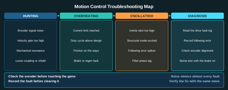
- Inertia Ratio and Servo Oscillation: Causes, Limits and Fixes
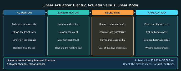
- Linear Actuators and Linear Motors: Selection for Machine Axes
- Harmonic Drive Gearbox Selection: Ratio, Repeatability and Life
Sources
- R+W Antriebselemente, Bellows Coupling Technical Data (torsional stiffness, backlash)
- KTR, Coupling Technical Documentation (alignment, TIR, balancing classes)
- Lovejoy, Flexible Coupling Selection and Alignment Guide
- IEC 60034-1, Rotating electrical machines: Rating and performance (shaft runout)
- ISO 9283, Machine tools: Test conditions for positioning accuracy and repeatability
Key Takeaways
- Rigid coupling backlash free selection starts with backlash: the angular play at the coupling when the drive direction reverses. A bellows coupling is backlash free by design; a jaw or spider coupling has a few arcminutes of it.
- Torsional stiffness is what decides whether the coupling is part of the control loop. A coupling of 5000 Nm per radian at 10 Nm of torque deflects 0.002 rad, which is 0.11 degrees and about 0.38 mm at a 200 mm radius.
- Alignment tolerance is the real selection criterion. Bellows and disc couplings take about 0.1 mm parallel and 0.05 mm angular, which is tight for a workshop-built machine bed.
- Total indicated runout of the motor shaft and the driven shaft must be budgeted separately. Above about 0.01 mm the runout shows up directly as a cyclic position error at every motor revolution.
- Balance matters above 3000 rpm. An unbalance of 5 g-mm at 3000 rpm produces a centrifugal force of about 4.9 N at the shaft, which is enough to excite a long axis.