Motion Control Troubleshooting: Hunting, Overheating and Oscillation
Key Takeaway
Motion control troubleshooting is a symptom-led exercise. Hunting that ignores speed is electrical, hunting that changes with speed is mechanical, overheating is always a current problem, and a fault at one speed and not another is a resonance.
Figure 1: Motion control troubleshooting map – hunting, overheating, oscillation, diagnosis
Table of Contents
1. Read the Fault First, Then the Machine
A motion control fault on a running machine is the situation where a technician has a choice: guess, or diagnose. Guessing costs hours and usually makes the machine worse, because the most common guess is to reduce the gain. Reducing the gain on a hunting axis makes the hunting worse, because the axis hunts because it is too stiff, not too soft. Motion control troubleshooting works from the symptom to the layer to the cause, and each of those three steps has a short enough list to be practical.
Step 1: the drive’s own diagnostics
Motion control troubleshooting works from the symptom to the layer to the cause, and each of those three steps has a short enough list to be practical. Before touching anything, read the fault. Modern servo drives record the fault code, the sub-code, the conditions at the time and the moment of occurrence. The sub-code is often the most informative part: an overcurrent fault with a “during acceleration” flag is a completely different problem from one with a “at constant speed” flag.
Record it before clearing it. A cleared fault code is a lost measurement, and the measurement was the whole point of the fault. If the drive has a fault history buffer, export it.
Step 2: the live values
Most drives display the following in real time, and these four numbers separate most causes:
| Value | What it tells you |
|---|---|
| Motor current (RMS) | Compare against the nameplate. Above rated means the load is bigger than calculated. |
| Following error | The single most useful number on a servo axis. See section 5. |
| DC bus voltage | Spiking above the overvoltage threshold during deceleration means the brake circuit is not working. |
| Motor temperature | Rising faster than the load warrants means current, not ambient, is the problem. |
Step 3: the symptom
Then classify the symptom into one of the six categories below. Each has a short and different list of causes.
2. Hunting and Buzzing
The one test that splits the list in half
Hunting is the most common complaint and the one most often misdiagnosed, and motion control troubleshooting starts by separating the electrical causes from the mechanical ones. Change the speed. If the buzz frequency stays exactly the same while the speed changes, the cause is electrical. If the frequency moves with the speed, it is mechanical. This one test eliminates half the possibilities.
| Cause | Frequency behaviour | Test |
|---|---|---|
| Encoder signal noise | Constant, often at an odd frequency | Run the axis with the encoder cable shield disconnected at the drive; if the noise changes, it is the cable |
| Poor shield termination | Constant, intermittent | Inspect the 360 degree surface mount; a pigtail termination is the most common fault in the whole machine |
| Current loop or encoder alignment | ||
| Constant, at a multiple of the electrical frequency | Check the drive’s motor parameter set against the motor nameplate | |
| Mechanical resonance | Changes with speed, or fixed at one speed | Slow through the speed range and watch the following error trace |
| Excessive velocity gain | Constant, grows with load | Reduce the velocity gain by 20 percent and re-run the standard move |
| Loose mechanical connection | Changes with load | Check every fastener in the drive train with the power off |
The order to check them
- Encoder cable and shield.Start here every time. Check the shield termination at the drive end, the connector locking, and the cable routing. Is the encoder cable running parallel to the VFD output cable anywhere? If so, reroute it.
- Encoder supply voltage.5 V DC or 24 V DC, measured at the motor end of the cable with the axis running, not at the drive. A drop of more than 0.5 V on a 5 V supply under load causes intermittent faults that look exactly like noise.
- Motor parameters.Compare the drive’s motor data against the motor nameplate: rated current, rated speed, rated torque, rotor inertia, and the encoder resolution. A wrong rotor inertia changes the tuning; a wrong encoder resolution changes the position scaling and will produce a following error that scales with speed.
- Mechanical tightness.Every coupling, every mounting bolt, every rail clamp. A loose coupling on a machine with a harmonic drive will destroy the gearbox.
- Velocity gain.Only after the above. And when you reduce it, do it in 20 percent steps and re-run the standard move each time.
A specific note on shielded cable
The most common installation error is a pigtail shield termination: the shield is twisted and pushed under a screw terminal. That does not work. The shield has to make a 360 degree surface contact with the connector shell. Buy the right connector with a strain relief clamp, not the cheap one with a screw. And terminate the shield at the drive end only: a shield bonded at both ends creates a ground loop through the machine frame, which is worse than no shield at all.
3. Overheating
The diagnostic
Heat is always a current problem until proven otherwise, and that single rule resolves most of the overheating cases in motion control troubleshooting. Measure the motor current on the drive display and compare it against the nameplate rated current. Then ask the question the current answers.
| Observation | Diagnosis | Action |
|---|---|---|
| Current above rated | The load is bigger than the calculation said | Find the mechanical cause, do not derate the motor |
| Current at rated, temperature still high | Thermal path or ambient problem | Check the mounting, the cabinet cooling and the ambient |
| Current well below rated, temperature high | Electrical loss, not mechanical load | Check for a shorted winding, a misaligned encoder giving wrong current feedback, or an incorrect motor parameter set |
| Temperature rises at standstill with no load | Brake not releasing, or a current loop fault | Check the brake current and the holding brake circuit |
The mechanical causes of excess current
- A dry or contaminated way.The most common cause by a wide margin. The lubrication schedule is on the machine and it is not being followed.
- A worn ball screw.Check for play in the nut by hand with the motor uncoupled. More than 0.05 mm of backlash means the nut is worn.
- A misaligned coupling.A coupling running at its misalignment limit generates a large radial force, and that force appears as extra motor torque.
- A brake that is not fully releasing.The brake is still dragging and the motor is fighting it. Check the brake release current and the air gap.
- A binding guide.Push the carriage by hand with the power off. It should move freely. If it is tight on one side, the mounting is off.
- A loose belt.A slack belt has to be taken up by the motor before the load moves, and that takes torque.
The ambient problem
Indian shop floors run at 40 to 45 degrees C in summer. Servo motors are typically rated at 40 degrees C ambient, and a drive in a sealed cabinet with no forced air can easily see 55 degrees C internally.
The derating rule of thumb: above 40 degrees C ambient, derate the motor by roughly 3 percent per degree C, and derate the drive by roughly 5 percent per degree C because the drive’s own semiconductor junction temperature rises with the cabinet temperature. A 40 degrees C rated drive in a 50 degrees C cabinet is at 50 percent of its rated current. This is a direct cost and it is often the reason a machine in a hot corner needs a bigger drive than the same machine in a cool corner.
The cabinet heat calculation
A servo drive dissipates roughly 3 to 5 percent of its rated power as heat. A 5 kW drive loses about 200 W. A closed cabinet with 200 W of heat needs 200 W of heat removal, which needs about 200 m^3/h of filtered airflow or a heat exchanger. A single 150 mm filter fan on a closed cabinet handles about 60 to 80 W of heat. The rule is that a filter fan needs an exhaust or a heat exchanger, and a filter fan alone in a closed cabinet will not keep up.
4. Position Errors and Drift
Case 1: the drive has lost the encoder reference
Position faults split into three distinct cases, and motion control troubleshooting is much faster once you know which of the three you have. Symptom: the drive reports an encoder fault or a lost reference, or the axis will not move without re-homing. The cause is one of four things:
- The encoder supply has dropped out or is marginal.
- The encoder cable has a broken conductor or an intermittent connector. Flex the cable while the axis is moving and watch for the fault to appear.
- The encoder coupling has slipped on the motor shaft. This happens when the coupling set screw was not tightened or was tightened onto a machined surface that is not flat.
- The drive has lost its absolute position reference, which on a multi-turn absolute encoder means a battery or a capacitor-backed memory failure.
Case 2: a large, consistent following error
Symptom: the axis reaches the target but the drive reports a following error throughout the move, and the position is consistently offset from the command. The cause is one of:
- The load is pushing the axis and the drive cannot resist it. A vertical axis with too little holding torque, or an axis being driven into a hard stop.
- The load is heavier than sized and the axis is saturating its torque limit. Check the current against the nameplate.
- The encoder is losing counts because of noise. The drive thinks it has moved further than it has, and the following error appears every cycle.
- The position scaling is wrong because the encoder resolution in the drive does not match the motor, or because the gear ratio or the screw lead in the parameters is wrong. This one is easy to check and it is often the answer.
Case 3: the position is right at rest and wrong after a move
Symptom: the axis holds position correctly when it is stopped, and the position after a move does not match the command. This is backlash. The cause is in the drive train, not in the drive:
- Backlash in a belt drive, a gear drive or a spline.
- A screw with a worn nut, which shows up as a bigger error at the end of a long move.
- A loose coupling where the coupling teeth or the clamp are slipping.
The test that confirms it: command the axis to a position, then command it back to the same position from the opposite direction, and compare the final positions. If they differ by the backlash amount, it is mechanical.
5. Faults at Specific Speeds
The confirming test
A fault that appears at one speed and at no other speed is a resonance, and it is the easiest pattern in motion control troubleshooting to recognise. Run the axis slowly from standstill through the suspect speed. If the fault appears at a repeatable speed and disappears above and below it, it is a resonance. This test takes two minutes and it is conclusive.
Why a resonance appears
Every machine has natural frequencies: the first bending mode of a long axis, the torsional mode of a shaft and coupling pair, the mode of a cross slide with a heavy carriage at the end, the mode of the machine’s own frame. When the command frequency sweeps through a natural frequency, the response amplitude grows sharply. At a large enough amplitude the axis overshoots, the drive’s following error limit trips, or the machine physically bangs.
Where the resonance comes from
- Excitation frequency.The profile generator’s frequency content. A trapezoidal profile with infinite jerk contains everything, which is why the S-curve helps. See the S-curve acceleration guide.
- Structural mode.The machine’s natural frequency. The most common culprit is a long axis with an overhang, and the second most common is a heavy carriage on a cross slide.
- Torsional mode.The coupling and shaft stiffness between the motor and the load. See the shaft coupling guide.
- Supply and drive effects.A DC bus ripple at twice the line frequency, which at 50 Hz is 100 Hz, can excite a mode near 100 Hz. The cure is a larger DC bus capacitor or a line reactor.
The fixes
- Notch filter in the drive.Most drives have a configurable notch filter with a centre frequency and a width. Set it to the measured resonance frequency plus 10 percent. This is the standard fix and it works.
- Low-pass filter on the velocity loop.Blunter than a notch. It attenuates everything above the corner frequency and it costs phase margin, so use it when the resonance amplitude is small.
- Change the speed.If the process allows, run above the resonance.
- Change the profile.A jerk-limited profile removes much of the high-frequency content that excites the mode.
- Fix the structure.The only real fix. Add a rib, shorten the overhang, support the far end of the screw, move the motor closer to the load, or stiffen the motor mounting plate.
Finding the frequency
Two methods that need no accelerometer. First, sweep the speed slowly and watch the following error trace on the drive display: a spike appears at the resonance. Second, with the axis coasting, put a dial indicator on the carriage and watch it through one revolution of the motor: if the indicator moves once per revolution, that is a runout problem rather than a resonance.
6. Intermittent Faults: Shielding and Earthing
The rules that eliminate most of them
- Terminate the encoder shield at the drive end only, with a 360 degree surface mount.A pigtail is the single most common cause of an intermittent axis fault.
- Do not run the encoder cable parallel to a VFD output cable.If they must cross, cross them at 90 degrees and keep the encoder cable in a separate trunking.
- Bond every metal part to a common earth bar with a dedicated strap.Do not rely on the cable tray, the mounting bolts or the structural steel as an earth path. Strap the machine base, the drive, the motor and the cabinet to one bar, and bond that bar to the plant earth with a single conductor.
- Do not create earth loops.If the machine is earthed at two points through the plant structure, the current in the structure between them flows through the machine, and that voltage appears on the encoder shield. One dedicated earth conductor per machine.
- Use a separate 24 V DC supply for the encoders and for the sensors, separate from the supply for the outputs. A contactor picking up dips the supply and the encoder sees the dip as a fault.
- Separate the drive’s power supply from the logic supply.On a 400 V axis, the drive’s DC bus can dump hundreds of volts of common mode noise onto the signal earth.
The test that confirms a shielding fault
Intermittent faults are the hardest part of motion control troubleshooting, and the answer is almost always in the shielding and the earthing rather than in the parameters. Run the axis continuously and wiggle the encoder cable at the drive end, then at the motor end, then along its length. Watch the fault log. A fault that appears when you wiggle a particular point has been found. Then flex the machine’s power cables, and the cabinet door, and the motor mount. If the fault appears when the cabinet door is moved, it is an earth or shield connection that is intermittent.
Another useful test: run the axis with the drive’s internal EMC filter enabled and then disabled, if the drive has the option. A change in behaviour points at the supply side rather than the signal side.
What to check when it is not the cable
- Loose connectors.Every connector on the axis, including the motor’s power connector. A connector that is not fully seated is the most common intermittent fault in any machine.
- Thermal effects.A fault that only appears after 20 minutes of running is thermal. Check the drive’s internal temperature, the motor temperature, and the cabinet temperature.
- Supply quality.Check the DC bus voltage ripple. A failing rectifier or a weak transformer produces a ripple that grows with load and causes intermittent faults.
7. Motion Control Troubleshooting: A Working Order That Saves Time
A fixed order of work turns motion control troubleshooting from guesswork into a procedure, and the order matters because each step eliminates a group of causes cheaply.
- Record everything before touching the drive.The fault code, the sub-code, the DC bus voltage, the motor current, the following error, the motor temperature. Write it down.
- Establish the symptom category.Hunting, overheating, position error, speed-specific fault, or intermittent. Each has its own short list.
- Check the drive’s motor parameters against the motor nameplate.Current, speed, torque, rotor inertia, encoder resolution. A wrong parameter here explains a surprising share of faults.
- Check the encoder cable, the shield termination and the encoder supply voltage at the motor end.With the axis running.
- Check the mechanical tightness and the alignment of the drive train.Every bolt, every coupling, and the free movement of the carriage by hand.
- Measure the current against the nameplate and separate the load problem from the heat problem.
- Only then change a parameter.One change at a time, and re-run the standard move after each one.
- Verify the fix with the standard move and record the peak following error, the settling time and the repeatability over 10 runs.
The rule about changing parameters
A fixed order of work turns motion control troubleshooting from guesswork into a procedure. Change one thing at a time and write down what you changed and what happened. An axis that has been “fixed” by four people each changing something is an axis nobody understands, and the next fault will take twice as long because nobody knows what the original settings were.
Before changing anything, save the drive parameters to a file or write them down. If the change makes it worse, put them back.
The standing record
Every machine should have a fault log, even a paper one in the cabinet. Write down the date, the symptom, the fault code, what was found and what was changed. Over two years that log turns into the most valuable document on the machine, and it turns the third occurrence of the same fault into a five-minute job.
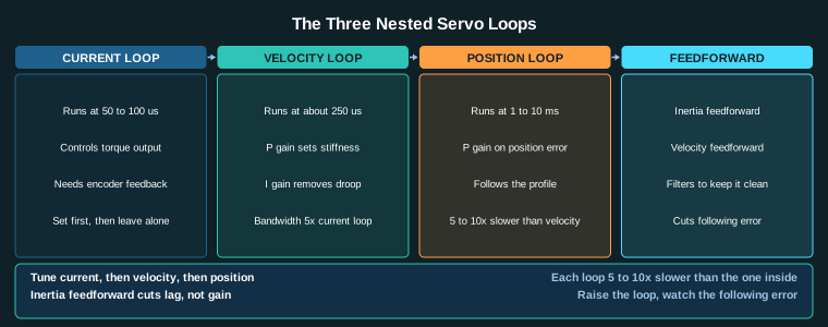
For the tuning side of the axis once the mechanical causes are cleared, the servo tuning guide covers the gain structure, and the inertia ratio guide covers the case where the hunting is a numbers problem rather than a noise problem.
Related Reading
- Industrial Motion Control: Complete Guide to Servo, Stepper and Axis Design
- Inertia Ratio and Servo Oscillation: Causes, Limits and Fixes
- Servo Tuning: Position, Velocity and Current Loops Explained
- Servo Drive Selection and Sizing: Power, Regeneration and Cable
Sources
- Yaskawa, Sigma-7 Servo Drive Troubleshooting Manual (fault codes, auto tuning, diagnostics)
- Rockwell Automation, Servo Drive Troubleshooting and Diagnostics
- Siemens, SINAMICS V90 Servo Drive Operating Instructions (diagnostics)
- IEC 61800-5-1, Adjustable speed electrical power drive systems: Safety requirements
- ISO 230-2, Test conditions for machine tools: Test methods for the accuracy of positioning of numerically controlled axes
Key Takeaways
- Motion control troubleshooting starts with the symptom: hunting at a fixed frequency regardless of speed points to the encoder signal, the shield termination or the current loop. Hunting that changes frequency with speed points to structure.
- Overheating is always a current problem until proven otherwise. Measure the drive’s reported current against the nameplate before touching the cabinet fan.
- A fault that appears at one speed and at no other speed is a mechanical resonance. The cheap fix is a notch filter, the right fix is stiffening the structure.
- Position drift splits into three cases: encoder reference lost, consistent following error under external load, and backlash in a belt or gear drive. The drive diagnostic tells you which one.
- Record the fault before clearing it. A cleared fault code is a lost measurement, and the measurement was the whole point of the fault.