LinuxCNC Hardware Configuration for a 3-Axis CNC Retrofit
Key Takeaway
A linuxcnc hardware configuration is three decisions stacked on top of each other: which Mesa controller board, which drive interface, and which feedback device. Pick the controller first because it fixes the drive and encoder options, then match the drives to the motor frames, then choose feedback at the motor for servo axes.
Figure 1: The four layers of a LinuxCNC 3-axis retrofit and the Mesa hardware that serves each one
Table of Contents
- 1. Why LinuxCNC for a Retrofit
- 2. The Controller Layer: Choosing the Mesa Board
- 3. The Drive Layer: Getting the Commands to the Motors
- 4. The Feedback Layer: Encoders, Counters and Position
- 5. I/O, Signal Conditioning and the Field Layer
- 6. Bringing It Up: A Practical Commissioning Order
- Related Reading
- Sources
1. Why LinuxCNC for a Retrofit
LinuxCNC is free software, and the hardware behind it is not, so the choice of boards is the choice that sets the cost of the whole control. This guide works through the three layers – controller, drive, feedback – and then the field layer, with the specific Mesa parts for each role and a commissioning order that lets each stage be trusted before the next one begins. The sections are written for the person who has to buy, wire and then maintain it.
LinuxCNC is the control software that most Indian retrofits end up on, and the reason is straightforward: it costs nothing, it runs on hardware you can buy, it drives both stepper and servo systems, and its documentation is good enough that a maintenance engineer can learn it. For a retrofit, those four facts matter more than the polish of a commercial control.
What LinuxCNC does not give you is a service network. A Fanuc-trained technician can fix a Fanuc. A LinuxCNC fault has to be fixed by whoever understands the machine and the software. The honest comparison is: the open route is cheaper and more flexible, and it places the knowledge inside your shop instead of inside a vendor’s office.
The three-layer model
Every LinuxCNC hardware configuration is the same three layers, and most mistakes come from mixing them up.
- The controller layer. A Mesa board (or a Raspberry Pi with a Mesa FPGA board) that runs real-time code, executes the motion plan, and reads the encoders. This is the brain and the servo loop.
- The drive layer. The interface from the controller to the motor: step/dir pulse trains, PWM plus direction for stepper drivers, or analogue velocity commands for analogue servo amplifiers.
- The feedback layer. Encoders and I/O counters that tell the controller where the axes actually are.
The controller layer makes the decisions. The drive layer carries them. The feedback layer corrects them. Configure them in that order and the problem is nearly always in the layer you checked last.
Section summary. The case for LinuxCNC on a retrofit is cost and serviceability, and linuxcnc hardware configuration is where both of those are either won or lost. The software is free and the hardware is available, but the hardware has to be chosen as a system. A linuxcnc hardware configuration that is picked part by part ends up with a board that cannot count the encoders the machine needs, and that is an expensive mistake to discover after wiring.
The total cost of a linuxcnc hardware configuration is the board, the host, the drives and the field hardware, and the board is the smallest part of it.
2. The Controller Layer: Choosing the Mesa Board
The Mesa board is the decision that constrains everything else, so start there.
The main options
| Board | Axes | Output types | Feedback inputs | Use it for |
|---|---|---|---|---|
| 7i76E | 6 servo (12 with expansion) | Analogue +/-10 V, plus step/dir and PWM | 6 quadrature, 6 serial smart encoder channels | The default choice for a servo retrofit |
| 7i92 | 4 step/dir | 4 step/dir plus 4 PWM | 4 quadrature | Stepper axes and low-cost servo drives |
| 7i74 | 4 servo (8 with expansion) | Analogue +/-10 V | 4 quadrature, 4 serial | Mid-size servo retrofit, older but well supported |
| 7i80 | 8 encoder counters | None | 8 quadrature, 8 serial smart | Feedback-heavy machines: glass scales, extra axes |
| 5i23 | None directly | 6 step/dir plus 6 PWM | None | Add-on output board to a 7i92 or 7i96 host |
| 5i24 | 1 or 2 | Step/dir | 4 quadrature, 2 serial | Small machines, single-axis add-on |
Which one for a 3-axis retrofit
For three servo axes with motor-mounted encoders, the 7i76E is the default. It runs six analogue servo axes on a single board, has six quadrature counters and six serial smart encoder channels, and has expansion headers for more axes. Its analogue outputs drive common analogue servo amplifiers directly, and its step/dir outputs drive stepper drivers and many digital servo drives.
For three stepper axes, the 7i92 is the standard. It has four step/dir channels and four quadrature counters, which covers three axes plus a spindle, with one axis spare for a fourth axis or a tool changer. It is also the board most often used with the 7i23 or 7i84 expansion to add more outputs.
For a mixed machine, servo on X and Y and stepper on Z, the 7i76E alone covers it, because the 7i76E has both analogue outputs and step/dir outputs on the same board. This is a common reason to prefer the 7i76E over assembling a 7i92 plus an expansion board.
The host computer
The Mesa board needs a host. Three options:
- Mesa FPGA board with a Raspberry Pi 4. The cheapest complete solution, and the most common in home-built machines. Adequate for 3 axes.
- Mesa 5i25 or 7i80 as a PCIe card in an industrial PC. The traditional industrial answer: an x86 industrial PC with the Mesa card in a PCIe slot, running a Linux distribution with the Mesa realtime kernel loaded. Better I/O expansion, more predictable timing, and the ability to run the software on a machine with more than two PCIe slots.
- A dedicated CNC controller box from a vendor who has assembled and tested the combination. This is the most expensive option and the least risky one, and for a shop that does not want to build it, it is the right one.
One practical note: the host must have a real-time capable kernel. LinuxCNC ships a realtime kernel, and running it on a generic consumer PC with aggressive power management is the most common cause of unexplained servo following errors. Disable CPU frequency scaling and the power management daemon on the host.
Section summary. The controller board is the decision that constrains everything else, so it comes first in linuxcnc hardware configuration. The 7i76E is the default for a servo retrofit because it carries both analogue servo outputs and step/dir outputs on one board, and the host choice – a Raspberry Pi, a PCIe card in an industrial PC, or a bought controller box – sets how much expansion you have and how predictable the timing is.
A 7i76E costs a few tens of thousands of rupees, and it decides what every other board in the cabinet is allowed to be.
3. The Drive Layer: Getting the Commands to the Motors
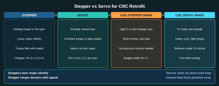
The controller produces a command; the drive turns it into motor current. The interface has to match the motor and the motor has to match the load.
Step/dir for steppers
A step/dir output is a pulse train plus a direction bit. The step frequency sets the speed and the pulse count sets the position. The controller generates it, the drive amplifies it into current, the motor moves.
Two settings decide whether a stepper retrofit works: microstepping and current setting. Microstepping smooths the motion and improves usable resolution, but it does not increase positioning accuracy, because the stepper’s actual position accuracy is set by the motor’s torque and the load. Set microstepping to 16 or 32 on a retrofit; beyond that the torque per microstep gets too low and the motor starts skipping under load.
Current setting is the more important one. Set it to the motor’s rated phase current, and never above it, because the motor’s rated current assumes a specific ambient temperature and a specific heat sinking. A stepper running at 100 percent of rated current in a closed cabinet in an Indian summer will overheat. The stepper versus servo guide covers the derating behaviour in detail.
Analogue servo amplifiers
An analogue servo drive takes a +/-10 V velocity command and a tachometer or encoder feedback signal, and it closes the velocity loop internally. The Mesa board provides the command signal and the feedback conditioning. The drive is matched to the motor by its power rating and by its feedback type: a drive that expects a tachometer cannot be used with an encoder without the right feedback module.
PWM servo drives
Many cost-effective digital servo drives for CNC accept step/dir plus an encoder feedback cable. The 7i76E’s step/dir outputs drive them directly, and the 5i23 or 7i84 does the same on a 7i92 host. This is the most common modern retrofit architecture in Indian job shops, because the drive is cheap and the encoder feedback closes the loop.
Spindle output
The spindle needs a speed command. Three ways to provide it:
- PWM. The 7i90 board provides 8 PWM outputs for spindle control, typically driving a VFD or an inverter with an enable input. This is the standard route for a VFD spindle.
- Analogue. The 7i76E analogue output can drive a VFD’s 0 to 10 V speed reference directly, if the VFD accepts that input.
- Step/dir. Some spindles take a step/dir speed command through a stepper-drive interface. Less common on a retrofit, but it works.
Whatever the interface, the spindle command must be scaled correctly. A VFD with a 0 to 10 V reference at 50 Hz per volt, for example, needs the software scale set to 50. Getting this wrong gives a spindle that runs at a fraction of the commanded speed or that will not start at all. The parameter setup is in the spindle VFD guide.
Section summary. The drive layer turns a controller command into motor current, and two settings decide whether it works: microstepping, which smooths the motion without improving true accuracy, and the current setting, which must be the motor’s rated phase current and no more. In linuxcnc hardware configuration, the interface type has to match the motor, and the spindle output has to be scaled correctly or the spindle runs at the wrong speed with no error message.
Budget the drive interface before the motor, because the interface decides which motor families you can even consider for a linuxcnc hardware configuration.
4. The Feedback Layer: Encoders, Counters and Position
Feedback is what makes a CNC a CNC. Without it the machine is an open-loop motion generator and the position is a hope.
Where to take feedback from
Three choices, in increasing order of accuracy:
- Motor-mounted encoder. The servo motor’s own encoder feeds back the motor rotor position. The controller then knows the screw position only if the mechanics between them are rigid and backlash-free. This is the standard for a retrofit, and it is what the 7i76E’s quadrature counters are for.
- Glass scale on the machine. The scale measures the actual table or saddle motion and sees every error in the drive train: screw wear, bearing play, and structural deflection under cutting load. This is the highest accuracy option and it is a retrofit addition for precision work. The encoder selection guide has the full comparison.
- External servo drive with its own loop. Some drives close the position loop internally and report position to the controller over a serial bus. This is the smart-serial encoder path on the Mesa boards.
Which counter board
The 5i21 gives 4 quadrature channels and 2 serial smart encoder channels. The 7i80 gives 8 quadrature and 8 serial. The 7i80 is the board to add when the machine has glass scales, a fourth and fifth axis, or a lot of extra quadrature feedback. It is also a PCIe card, so it slots into the same industrial PC as the 5i25.
A quadrature encoder with P pulses per revolution and 4x decoding gives 4P counts per revolution. The resolution in arcseconds is 3600 x 3600 / (4P). For P = 1000 that is 3600000 / 4000 = 900 arcseconds per count, or 0.25 degrees. For P = 2500, 4P = 10000, and the resolution is 360 arcseconds, or 0.1 degrees. To get from encoder counts to machine microns you also need the gear ratio and the screw lead. For a 10 mm lead screw with no gearbox, one screw revolution is 10 mm, and with 10000 counts per revolution that is 10000 counts per 10 mm, or 0.001 mm per count.
Absolute encoders
An absolute encoder reports position without a reference, so the machine does not need a homing cycle at startup. On the 7i76E, absolute encoders connect over the Mesa smart-serial protocol, which is a differential data link carrying power and data on a single small connector. A serial absolute encoder from the same family as the servo motor replaces the incremental encoder and gives power-on position. This removes one of the most common retrofit complaints, which is the machine that will not start because the operator forgot to home it.
Section summary. Feedback is what separates a CNC from a pulse generator, and it is the layer where linuxcnc hardware configuration quietly determines the achievable accuracy. A motor encoder infers the table position through the mechanics; a scale on the machine measures it and sees screw wear, bearing play and deflection. The counter board has to be chosen to match the number and type of feedback channels the machine actually needs.
The feedback layer is where the budget for a linuxcnc hardware configuration is either justified or wasted, and the count ratio test settles it in twenty minutes.
5. I/O, Signal Conditioning and the Field Layer
The controller also has to talk to the machine: switches, buttons, solenoids, contactors, coolant and spindle start. The field layer is where most retrofit reliability problems are created.
Digital I/O boards
- 7i85. 12 digital inputs and 8 digital outputs, 5 V logic, intended for closer-coupled field I/O in the same cabinet as the controller.
- 7i70. 48 inputs and 48 outputs on a single card, for a machine with a lot of I/O, typically with opto-isolation modules in the field.
- 7i92. 8 digital inputs and 8 digital outputs in addition to its motion outputs.
Isolation is not optional
Every field input on a retrofit should be opto-isolated, and the isolation should be at the field end. A limit switch wired directly into a 5 V logic input shares a common ground with the motion electronics, and a 24 V solenoid coil in the same cabinet will induce a spike that the controller sees as a real input change. The symptom is an axis that stops for no reason, or a machine that faults when the coolant pump starts.
The 5 V logic side of the Mesa board is the sensitive part. Keep it away from the contactors, the VFD output cable and the motor power cables. Use separate cable trays, and bond the cabinet earth with short wide straps.
Field devices
- Limit switches. Inductive proximity sensors are more reliable than mechanical limit switches on a retrofit because they have no mechanical wear and no contact bounce. Set them 2 to 3 mm from a steel flag. The selection and wiring rules are in the limits and homing guide.
- E-stop. The E-stop must not go through the software path. It goes to a safety relay that removes the drive enable and the contactor power directly. The safety function should meet the requirements of ISO 13849-1, and a Category 3 or PL d architecture with a monitored safety relay is the normal answer. The E-stop mushroom must be a positive-opening device, so that a welded contact cannot hold the circuit closed.
- Spindle and coolant solenoids. These are inductive loads. Use a solid-state output with a suppression diode across the coil, or a relay output with an RC snubber. A coil with no suppression is the classic source of the intermittent controller reset that gets blamed on the power supply.
Shielded cable and grounding
Follow a simple discipline and the EMC problems largely disappear:
- Motor power in shielded cable, shield bonded at the drive end only for a drive with a single earth terminal, or at both ends if the drive specifies it. Read the drive manual on this point; getting it wrong is worse than not shielding.
- Encoder feedback in shielded twisted pair, from the drive or the motor to the controller, not spliced, and kept 200 mm away from the VFD output cable.
- Field I/O in shielded cable for anything longer than 3 m, with the shield earthed at the controller end.
- Earth: one dedicated earth conductor from the cabinet to the plant earth, with short wide braided straps between the cabinet, the drives, the controller and the panel door.
Section summary. The field layer is where most retrofit reliability problems are created, and it is the part of linuxcnc hardware configuration that gets the least attention. Opto-isolation at the field end, suppression across every solenoid coil, screened and separated cabling, a positive-opening E-stop into a monitored safety relay and inductive rather than mechanical sensors are the rules that decide whether the machine is quiet or a source of unexplained faults.
Field I/O boards are cheap, and the money in a linuxcnc hardware configuration is better spent on isolation, cabling and terminations than on more digital points.
6. Bringing It Up: A Practical Commissioning Order
Bring the machine up in a fixed order, and never skip a stage because the machine appears to work. The order below is designed so that each stage can actually be trusted when the next one starts.
Stage 1: I/O, with no motion
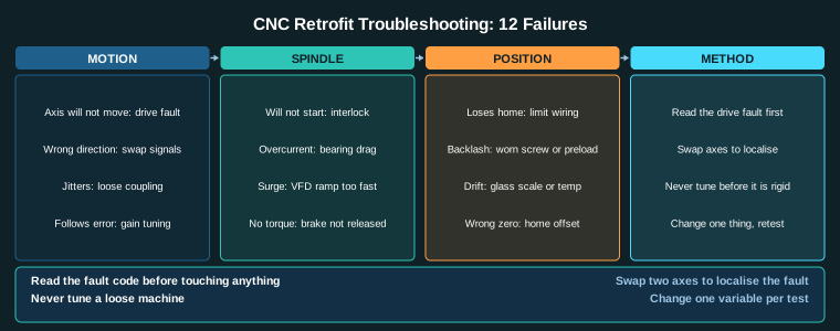
Power the controller with the drives disconnected. Walk every input with a meter or a tester: press each button, toggle each switch, actuate each sensor. The software display must match the physical device. Fix every mismatch before going further. Nine times out of ten a “the machine does random things” complaint is a swapped input in the I/O list, not a software fault.
Stage 2: outputs, one at a time
Command each output individually with the motion still disabled. Confirm the contactor pulls in, the coolant starts, the spindle enable engages. Confirm the feedback: a closed loop on the contactor auxiliary contact is better than an open loop.
Stage 3: single axis, manual jog
Set the software limits generously wide. Jog one axis in one direction only, at a low speed. Watch the following error. If it climbs steadily instead of staying flat, stop: the axis is not moving under control. Check the encoder wiring first, then the motor phase, then the parameter scaling.
Stage 4: single axis, full travel
Slowly extend the travel. Watch for the following error rising near the end of travel. That is usually a mechanical issue, an end-of-travel bump, or a loose coupling. Do not go to full speed until the following error is stable across the whole travel.
Stage 5: all axes, homing
Home one axis, then another, then all three. Then do a move from home to home and back, and check the return position with a dial indicator and a test bar. If the return position shifts by more than 0.01 mm, the mechanical side is not yet ready.
Stage 6: backlash measurement and compensation
Measure the backlash on each axis with a dial indicator and a spring scale before enabling compensation, so you know the number you are compensating. Then enable it and verify by measuring a test piece cut in both directions.
Stage 7: acceleration and feed limits
Set the maximum velocity, the maximum acceleration and the jerk limit from the motor’s actual capability, not from the machine’s stated capability. A common mistake is to set acceleration in the INI file at a value the drive cannot achieve, and then the drive reports a following error fault that looks like a software problem.
Stage 8: the cutting test
Cut a real part in the real material. Watch the following error during the cut. A stable following error during cutting is the sign that the axis can absorb the load. Then record the acceptance results. The accuracy test method is set out in the parent retrofit guide, and the machine acceptance procedure for a lathe is in the lathe retrofit guide.
Where to read next
The Mesa documentation and the LinuxCNC documentation are the authoritative references for board pinouts and for the INI and HAL files. The servo motor selection guide covers the drive sizing that determines what the controller has to command, and the encoder selection guide covers the feedback layer in detail. For a worked end-to-end example of an open-control retrofit, the industrial motion control guide sets out the whole stack.
Section summary. Bringing it up in a fixed order is what makes linuxcnc hardware configuration debuggable: I/O with no motion, outputs one at a time, a single axis on manual jog, a single axis over full travel, then homing, then backlash, then the acceleration limits, then the cutting test. Each stage can be trusted when the next one starts. Skip a stage because the machine appears to work, and the fault you find later will be in the stage you skipped.
A linuxcnc hardware configuration that is commissioned in eight fixed stages will find its own faults, and a linuxcnc hardware configuration that is commissioned by pressing buttons will not.
Related Reading
- CNC Machine Retrofit: Complete Guide
- Servo Motor Selection for CNC Retrofit
- Encoder Selection for CNC Axes
- Limit Switches, Homing and Proximity Sensors
- CNC Retrofit Cost Calculator
Sources
- LinuxCNC Documentation, Hardware Compatibility
- Mesa Electronics, 5i/7i Series Motion Hardware
- LinuxCNC Documentation, HAL and INI Files
- Mesa Electronics, THRS-21 Line Scale Encoder
Key Takeaways
- Choose the Mesa controller board first, because it fixes which drive interfaces and encoder counters you can use downstream.
- The 7i76E gives six axes of servo control with expansion to 12; the 7i92 and 7i74 are the step/dir and quadrature servo options.
- Use the 5i23 or 7i84 for step/dir outputs, the 7i96 for analogue servo amplifiers, and the 7i90 for spindle PWM output.
- The 5i21 and 7i80 are encoder counter boards; count 4 or 8 channels depending on how many axes need feedback.
- Do not run encoder feedback and step/dir output on the same axis unless the drive itself is closed loop; the software cannot close a loop it cannot measure.