Key Takeaway: Master the essential oscilloscope skills — setting timebase and voltage per division, selecting the right trigger mode, connecting probes correctly, and interpreting waveform measurements — to diagnose circuits with confidence using any modern digital storage oscilloscope.
Table of Contents
1. What Is an Oscilloscope?
An oscilloscope is the single most powerful diagnostic tool in any electronics engineer’s arsenal. Unlike a digital multimeter, which shows you a single numerical value, an oscilloscope graphs voltage over time in real time. This lets you see the signal: its shape, amplitude, frequency, rise time, noise, glitches, and timing relationships between multiple signals.
Learning how to use an oscilloscope is an essential skill for anyone working with electronics — whether you are debugging an STM32 microcontroller circuit, tuning a PID controller, or troubleshooting a switch-mode power supply. Modern digital storage oscilloscopes (DSOs) have made the learning curve much gentler with auto-setup features, on-screen measurements, and USB connectivity.
2. Essential Controls and Settings
Every oscilloscope, regardless of brand or price point, has five fundamental control sections you must understand:
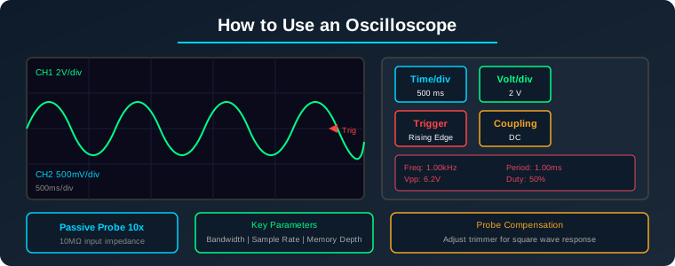
1. Vertical System (Volts/div): Controls how many volts each vertical division represents. For a 5V peak-to-peak signal, set this to 1V/div or 2V/div so the waveform fills about 60-80% of the screen. Too high and the waveform looks flat; too low and it clips off-screen.
2. Horizontal System (Time/div): Controls the time scale — how many milliseconds or microseconds each horizontal division represents. For a 1kHz sine wave (1ms period), start at 200μs/div to see about 5 complete cycles. Use the horizontal position knob to shift the waveform left or right.
3. Trigger System: The most misunderstood but critical control. Trigger tells the oscilloscope when to start drawing. Set trigger source to the signal channel (CH1 or CH2), trigger level to about 50% of the signal amplitude, and slope to rising edge. A stable trigger produces a rock-solid waveform; incorrect trigger settings produce a blurry or rolling display.
4. Coupling (AC/DC/GND): DC coupling passes all signal content. AC coupling blocks the DC component and shows only AC variations — useful when you want to see ripple on a 5V supply. GND coupling shows the zero-volt reference level.
5. Channel Controls: Most oscilloscopes have 2 or 4 channels. Each channel has its own volts/div setting, position control, and coupling option. Use CH1 for your primary signal and CH2 for a secondary signal like a clock or trigger.
3. Probe Selection and Compensation
The probe is just as important as the oscilloscope itself. Most scopes come with 10x passive probes — these attenuate the signal by 10x but offer 10MΩ input impedance, which minimizes circuit loading. Here is what you need to know:
1x vs 10x: Always use the 10x setting unless measuring very low-voltage signals (under 100mV). The 1x setting reduces bandwidth significantly and loads the circuit more. Set the probe switch to 10x and tell the oscilloscope the probe is 10x (usually via the channel menu).
Probe Compensation: Before making any critical measurement, compensate your probe. Clip the probe tip to the scope’s built-in 1kHz square wave reference (usually marked with a 1-2V square wave symbol). Adjust the small trimmer screw on the probe until the displayed square wave has perfectly flat tops and sharp corners. Over-compensated probes show peaked corners; under-compensated probes show rounded corners.
Ground Lead: Keep the ground lead as short as possible. A long ground lead acts as an antenna and picks up noise, especially at high frequencies. Use the included spring ground tip for high-frequency work.
4. Making Your First Measurements
Follow this step-by-step process for your first how to use an oscilloscope practice session:
Step 1: Power on the scope and connect a 10x passive probe to CH1. Clip the probe to the scope’s calibration output (1kHz square wave).
Step 2: Press the Auto Set button. The scope will automatically set volts/div, time/div, and trigger. Note what it chose.
Step 3: Adjust time/div to show 2-3 complete cycles. Adjust volts/div so the waveform fills about 80% of the screen vertically.
Step 4: Read the automatic measurements: Vpp (peak-to-peak voltage), Frequency, Period, and Duty Cycle. Most modern scopes display these as on-screen readouts.
Step 5: Switch to manual trigger mode. Set trigger level to 50% of signal amplitude. Observe how the waveform stabilizes. Now turn the trigger level knob slowly — notice how the waveform becomes unstable when the trigger level is outside the signal’s voltage range.
The typical measurement sequence for any signal is: connect probe → set volts/div → set time/div → adjust trigger → read measurements.
5. Advanced Measurement Techniques
Once comfortable with basic operation, these advanced techniques will significantly expand your diagnostic capability:
Cursor Measurements: Use manual cursors to measure precise voltage differences, time intervals, or rise/fall times. Place cursor X on the waveform’s rising edge at 10% amplitude and cursor X on the same edge at 90% amplitude to read rise time directly.
Math Functions: Use FFT (Fast Fourier Transform) to view the frequency spectrum of your signal — excellent for finding noise sources and harmonic distortion. Use the subtract function (CH1 – CH2) for differential measurements.
Persistence: Enable infinite persistence to see signal variation over time. This reveals intermittent glitches, jitter, and noise that are invisible in normal mode. Useful for tracking down intermittent faults.
Single-Shot Capture: For capturing one-time events (like a power-up transient), set trigger mode to Single, connect the probe, arm the scope, then power on the device. The scope captures and displays the event, then stops.
Serial Decoding: Many mid-range scopes can decode I2C, SPI, UART, and CAN bus signals. Connect the appropriate channels, set the protocol parameters (baud rate, voltage levels), and the scope will display decoded data alongside the waveform.
6. Common Mistakes and How to Avoid Them
| Mistake | Effect | Fix |
|---|---|---|
| Probe in 1x mode | Limited bandwidth, circuit loading | Switch to 10x and set scope to 10x |
| Long ground lead | Excessive noise at >10MHz | Use ground spring tip |
| Uncompensated probe | Inaccurate amplitude and rise time | Compensate before each session |
| Wrong trigger settings | Unstable, rolling display | Use Auto Set or manual 50% level |
| Sampling too low | Aliasing — signal looks wrong | Ensure sample rate > 5x signal frequency |
Frequently Asked Questions
What bandwidth oscilloscope do I need as a beginner?
For general electronics work, a 50-100MHz bandwidth is ideal. The rule of thumb is 5x the highest frequency you plan to measure. For microcontroller work (STM32, Arduino at 8-72MHz), a 100MHz scope is recommended.
How is an oscilloscope different from a logic analyzer?
An oscilloscope shows analog voltage over time — essential for checking signal quality, noise, and analog behavior. A logic analyzer only shows digital high/low states but captures many more channels (16-32+) simultaneously. For embedded debugging, both tools complement each other.
Can I measure current with an oscilloscope?
Indirectly, yes. Use a current probe (Hall-effect or current transformer) that outputs a voltage proportional to current. Alternatively, measure voltage across a known shunt resistor and calculate current using Ohm’s Law. Never connect a standard voltage probe across a current-carrying conductor.
What is the difference between analog and digital storage oscilloscopes?
Analog scopes display signals in real time using a CRT beam. Digital scopes (DSOs) sample the signal, digitize it, store it in memory, and display the reconstructed waveform. DSOs offer single-shot capture, storage, measurements, and FFT — making them vastly superior for modern electronics work.
Sources
- Keysight Oscilloscope Fundamentals Guide
- Tektronix Oscilloscope Probe Basics Primer
- Rohde & Schwarz Oscilloscope Educational Content
- Rigol Digital Oscilloscope Product Guide
Disclosure: This post contains affiliate links. We may earn a small commission if you purchase through these links at no additional cost to you.