Key Takeaway: Most CNC router motor problems fall into three categories — stepper motor drive issues (skipped steps, vibration, overheating), spindle/VFD faults (won’t start, speed fluctuation, noise), or motion controller signal problems — and can be systematically diagnosed using a voltage-first approach without expensive test equipment.
Table of Contents
1. Stepper Motor Problems and Solutions
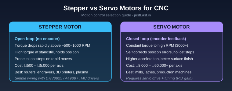
Stepper motors are the workhorses of most hobby and prosumer CNC routers. When something goes wrong, the symptoms are usually unmistakable. Here are the most common issues and their fixes.
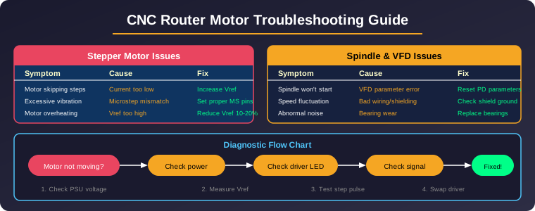
Skipped Steps (Position Loss): The most frustrating CNC problem. The motor makes a buzzing or grinding sound, and the axis drifts from its expected position. This is almost always caused by insufficient motor current. Check that your driver (DRV8825, TB6600, or DM542) is set to deliver at least 70% of the motor’s rated current. For a typical NEMA23 stepper rated at 2.8A, set the driver to 2.0-2.4A.
Excessive Vibration or Resonance: If the motor vibrates noisily at certain speeds, you are hitting the motor’s natural resonance zone. Solutions include enabling half-current or automatic current reduction, increasing microstepping (1/16 or 1/32), or using a TMC2209/TMC5160 driver with stealthChop technology. For existing builds, adjusting the acceleration profile in GRBL or Mach3 to skip through resonance bands quickly is the cheapest fix.
Motor Overheating: Stepper motors run warm — 80-90°C surface temperature is normal. If you cannot keep your finger on the motor for more than 5 seconds, the current is too high. Reduce Vref by 10-20%, or enable the driver’s automatic current reduction (standby mode) which cuts current by 50% when the motor is idle.
Motor Does Not Move: Check the enable pin. Most drivers have an ENABLE signal that must be LOW (grounded) to activate. Also verify the STEP and DIR pins have clean 5V logic signals — use an oscilloscope if available. For GRBL-based controllers, the $X unlock command must have been issued after reset.
2. Driver Current (Vref) Tuning
Setting the correct motor current via Vref is the single most important tuning step for any CNC router motor troubleshooting session. Each driver chip has a specific Vref calculation:
| Driver | Vref Formula | Example (2A Motor) | Max Current |
|---|---|---|---|
| A4988 | Vref = Current x 8 x Rs | Vref = 1.0V (Rs=0.05) | 2A |
| DRV8825 | Vref = Current x 5 x Rs | Vref = 1.5V (Rs=0.1) | 2.5A |
| TB6600 | Vref = Current x 1.25 | Vref = 2.5V | 4A |
| DM542 | Peak Current = Vref x 2 | Vref = 1.0V | 4.2A |
| TMC2209 | IRMS = Vref / (2.5 x Rs) | Vref = 1.5V (Rs=0.11) | 2A RMS |
To measure Vref: place your multimeter’s negative probe on a ground pin (typically the power supply negative terminal), and the positive probe on the potentiometer wiper (the centre pin of the trimmer pot) on the driver board. Turn the pot clockwise to increase, counter-clockwise to decrease. Always measure with the driver powered and motors enabled.
3. Spindle and VFD Troubleshooting
The spindle motor and its variable frequency drive (VFD) have their own set of common problems:
Spindle Won’t Start: Check that the VFD’s PD parameters match your spindle’s specifications. For a typical 1.5kW water-cooled spindle (220V, 400Hz, 24000 RPM), the critical parameters are PD003 (main frequency: 400Hz), PD004 (base frequency: 400Hz), PD005 (max voltage: 220V), PD006 (mid frequency: 2.5Hz), PD010 (acceleration: 3-5 seconds), and PD011 (deceleration: 3-5 seconds). Incorrect PD parameters are the #1 cause of “spindle won’t start” calls.
Speed Fluctuation: If the spindle RPM varies during a cut, inspect the wiring between VFD and spindle. Use shielded, twisted-pair cable rated for VFD output. Ensure the shield is grounded at the VFD end only (NOT both ends, which creates ground loops). Also check that the 0-10V speed control signal from the CNC controller is stable — a noisy PWM-to-analog converter can cause jitter.
Abnormal Noise: Grinding or rattling from the spindle typically means bearing wear. Water-cooled spindles accumulate debris in the coolant passages, leading to uneven thermal expansion. Replace sealed ceramic bearings, and flush the coolant system with distilled water. For air-cooled spindles, check that the cooling fan is operational.
VFD Error Codes: Common VFD errors include OC (over-current, usually from shorted motor windings), OH (overheat, check cooling), and LU (low voltage, check input power). Document the exact error code and consult your VFD manual — most issues are parameter-related, not hardware failures.
4. Wiring and Shielding Issues
Poor wiring is responsible for roughly 40% of all CNC router motor problems. Follow these guidelines:
Power Supply: A 36V switched-mode power supply is ideal for most NEMA23 setups. Undersized power supplies cause voltage sag during acceleration, which manifests as skipped steps on all axes simultaneously. Calculate total current: (sum of motor rated currents) x 0.67. For four 2.8A motors, you need at least 7.5A supply — use a 10A unit for margin.
Signal Cables: STEP and DIR signals from the motion controller (Arduino/GRBL, Mach3 parallel port, or Ethernet SmoothStepper) must use twisted-pair shielded cable. Separate signal cables from motor power cables by at least 10cm. Crossing at 90 degrees is acceptable if necessary.
Grounding: Star-ground all earth connections — spindle VFD chassis, controller enclosure, and power supply frame — to a single point. Ground loops through multiple paths create mysterious intermittent issues that are extremely hard to diagnose.
5. Motion Controller Signal Problems
Sometimes the motor and drive are fine, but the motion controller is sending bad signals:
GRBL Feed Hold Issues: If motors stop responding after a feed hold or resume, check that the RESET pin is properly pulled high through a 10kΩ resistor. Floating RESET pins pick up noise and cause random resets.
Pulse Frequency Too High: GRBL’s maximum step pulse frequency is determined by $5 (step pulse, microseconds) and $26 (step pulse length). For drivers requiring a minimum 5μs pulse (most TB6600 and DM542), set $5=1 (active low) and $26=5. For TMC drivers with 1μs minimum, set $26=2 for faster acceleration.
EMI Interference: If the CNC runs fine with the spindle off but loses steps when the spindle starts, you have electromagnetic interference. Solutions: ferrite cores on all motor cables, shielded spindle cable, separate ground paths, and moving the controller board into a metal enclosure.
6. Step-by-Step Diagnostic Process
When you encounter any CNC router motor problem, follow this systematic diagnostic flow:
- Visual inspection: Check for loose connectors, burnt smells, visible damage on driver boards. Look for the driver status LED — a solid green/blue usually means healthy, blinking or off indicates a fault.
- Power check: Measure the power supply voltage at the driver input terminals under load. A 36V supply should read 34-38V. Under 30V indicates a failing or undersized supply.
- Vref measurement: Measure and verify the Vref voltage matches the formula for your driver and motor combination. This fixes 60% of stepper motor problems.
- Signal test: With the motor disconnected, use an oscilloscope or logic analyzer to verify clean step pulses at the driver input. Pulses should be clean square waves with sharp edges and no ringing.
- Swap test: Swap the suspect driver with a known-good one from another axis. If the problem follows the driver, replace it. If the problem stays with the motor cable, check wiring.
- Isolation test: Run the spindle alone without motion, then motion alone without spindle. This isolates EMI issues.
For more on CNC machine setup, see our guide on CNC Dust Collection Setup Guide 2026 and CNC Control Software Comparison.
Frequently Asked Questions
Why does my CNC router lose steps only during fast moves?
This indicates acceleration is too high or motor current is marginal. Reduce GRBL’s $120/$121/$122 (max acceleration) values by 25%, and verify Vref is at least 70% of rated current. Fast moves demand maximum torque from the stepper motor, and insufficient current causes the rotor to fall behind the magnetic field.
Can a bad stepper motor driver cause spindle issues?
Indirectly, yes. A failing driver can draw excessive current from the shared power supply, causing voltage sag that affects the spindle VFD. However, the far more common scenario is that spindle EMI interferes with the stepper driver signals. Fix the EMI first — separate power supplies for spindle and steppers is the definitive solution.
How often should I replace spindle bearings?
For a hobby CNC used 10-20 hours per week, replace spindle bearings every 12-18 months. For production use (40+ hours/week), every 6-8 months. Signs of bearing wear include: audible grinding, visible runout at the collet (check with a dial indicator), and spindle body temperatures exceeding 60°C.
Is it worth upgrading from DRV8825 to TMC2209?
Absolutely, if you value quiet operation and smooth motion. TMC2209’s stealthChop2 reduces motor noise by 80-90%, and the higher maximum current (2A RMS vs 1.5A for DRV8825) provides better torque. However, TMC drivers are more sensitive to voltage spikes — always add a 47μF electrolytic capacitor near the driver’s power input.
Sources
- TMC2209 Stepper Driver Datasheet — TRINAMIC/ADI
- GRBL Configuration Guide — GitHub
- A4988 DMOS Microstepping Driver — Allegro MicroSystems
- VFD Parameter Setting Guide for CNC Spindle Motors
Disclosure: This post contains affiliate links. We may earn a small commission if you purchase through these links at no additional cost to you.