Key Takeaway: Learn how to control bipolar stepper motors using the DRV8825 stepper motor driver with an Arduino. This complete guide covers wiring diagrams, current limiting, microstepping configuration, and ready-to-use Arduino code for NEMA 17 and NEMA 23 motors.

Table of Contents
1. System Overview
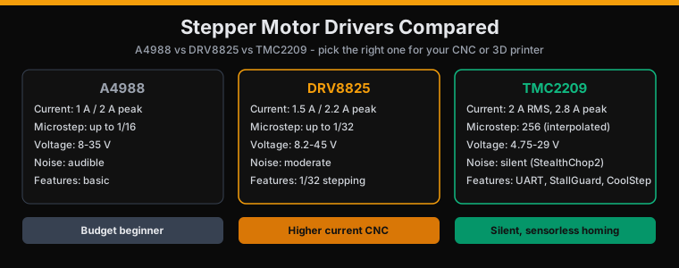
The DRV8825 stepper motor driver from Texas Instruments is a versatile driver IC capable of driving bipolar stepper motors up to 2.5A per coil with a supply voltage range of 8.2V to 45V. It features built-in microstepping up to 1/32 step, making it ideal for CNC machines, 3D printers, and precision motion control systems.
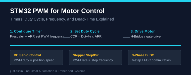
Unlike the older A4988 driver, the DRV8825 offers higher current capacity, lower RDS(on) MOSFETs for better thermal performance, and support for 1/32 microstepping. It uses a simple STEP and DIR interface that works seamlessly with any microcontroller. The driver handles all the complex current chopping and PWM generation internally, so you only need to send step pulses and direction signals from your Arduino.
This guide covers everything you need to get your DRV8825 stepper motor driver running with an Arduino, including the critical current limiting step that most tutorials skip.
2. Hardware Required
- Arduino Uno, Nano, or any 5V Arduino board
- DRV8825 stepper motor driver module (with heatsink)
- Bipolar stepper motor (NEMA 17 or NEMA 23 recommended)
- 12V DC power supply (3A minimum for most applications)
- 100µF electrolytic capacitor (16V or higher rating)
- Breadboard and jumper wires
- Small flathead screwdriver (for trim pot)
- Digital multimeter
Important: Always use a heatsink on the DRV8825. Without proper heat dissipation, the driver will enter thermal shutdown during extended operation, especially at currents above 1A per coil.
3. Wiring the DRV8825
The DRV8825 module has two sets of connections: the logic side (to Arduino) and the power side (to motor and power supply).
Logic Connections (to Arduino):
- STEP (D2): Pulse this pin to move the motor one step (or microstep). Each rising edge triggers one step.
- DIR (D3): Direction control. HIGH = clockwise, LOW = counter-clockwise.
- ENABLE (D4): LOW enables the driver outputs. HIGH disables (motor freewheels).
- M0 (D5), M1 (D6), M2 (D7): Microstep resolution selection.
- VCC: Connect to Arduino 5V (powers the internal logic).
- GND: Common ground with Arduino.
Power Connections:
- VMOT: Motor power supply, 8.2V to 45V DC.
- GND: Power ground — connect to the negative terminal of your power supply.
- A1, A2: First motor coil (typically black and green wires on NEMA 17).
- B1, B2: Second motor coil (typically red and blue wires on NEMA 17).
- FAULT: Open-drain output that goes LOW when the driver detects over-current or thermal shutdown.
Critical! The Decoupling Capacitor
You must place a 100µF electrolytic capacitor between VMOT and GND, as close to the driver module as possible. Stepper motors draw large current spikes that can damage the driver and cause erratic behavior without proper decoupling. Omitting this capacitor is the #1 cause of DRV8825 failures.
4. Setting the Current Limit
This is the most important step in using the DRV8825 stepper motor driver. The driver does not have current-sensing resistors; instead, current is set by a reference voltage (VREF) measured at the trim pot.
Formula:
I_max = VREF × 2So VREF = I_max / 2. For a motor rated at 1.5A per phase, set VREF to 0.75V.
Procedure:
- Power the driver (connect VMOT to your power supply).
- Connect a multimeter probe to the trim pot center pin (or the test point labeled VREF).
- Connect the other probe to GND.
- Turn the trim pot slowly while watching the voltage reading.
- For a NEMA 17 motor rated at 1.5A: set VREF to 0.75V.
- For a NEMA 23 motor rated at 2.5A: set VREF to 1.25V.
Safety tip: Set the current to about 80% of the motor’s rated current for reliable long-term operation. Running at 100% current requires active cooling and reduces motor life.
5. Microstepping Configuration
Microstepping reduces vibration and improves positioning resolution by dividing each full step into smaller increments. The DRV8825 supports full-step through 1/32-step modes, selected via the M0, M1, and M2 pins:
| M2 | M1 | M0 | Microstep Resolution |
|---|---|---|---|
| LOW | LOW | LOW | Full step (1/1) |
| LOW | LOW | HIGH | 1/2 step |
| LOW | HIGH | LOW | 1/4 step |
| LOW | HIGH | HIGH | 1/8 step |
| HIGH | LOW | LOW | 1/16 step |
| HIGH | LOW | HIGH | 1/32 step |
| HIGH | HIGH | LOW | 1/32 step |
| HIGH | HIGH | HIGH | 1/32 step |
For most CNC and 3D printer applications, 1/16 microstepping offers the best balance of smooth motion, torque, and step rate. Use 1/32 when vibration must be minimized (e.g., precision optics or lab equipment).
6. Arduino Code
Here’s a complete Arduino sketch for controlling the DRV8825 with adjustable speed, direction, and microstepping:
// DRV8825 Stepper Motor Driver - Complete Control
#define STEP_PIN 2
#define DIR_PIN 3
#define ENABLE_PIN 4
#define M0_PIN 5
#define M1_PIN 6
#define M2_PIN 7

void setup() {
  pinMode(STEP_PIN, OUTPUT);
  pinMode(DIR_PIN, OUTPUT);
  pinMode(ENABLE_PIN, OUTPUT);
  pinMode(M0_PIN, OUTPUT);
  pinMode(M1_PIN, OUTPUT);
  pinMode(M2_PIN, OUTPUT);

  // Enable driver
  digitalWrite(ENABLE_PIN, LOW);

  // Set 1/16 microstepping: M2=HIGH, M1=LOW, M0=LOW
  digitalWrite(M2_PIN, HIGH);
  digitalWrite(M1_PIN, LOW);
  digitalWrite(M0_PIN, LOW);

  Serial.begin(9600);
  Serial.println("DRV8825 Ready");
}

void loop() {
  // Rotate 200 steps clockwise (1 revolution at 1/16 stepping = 3200 steps)
  digitalWrite(DIR_PIN, HIGH);
  for(int i = 0; i < 3200; i++) {
    digitalWrite(STEP_PIN, HIGH);
    delayMicroseconds(500);  // Speed control
    digitalWrite(STEP_PIN, LOW);
    delayMicroseconds(500);
  }
  delay(1000);

  // Rotate 200 steps counter-clockwise
  digitalWrite(DIR_PIN, LOW);
  for(int i = 0; i < 3200; i++) {
    digitalWrite(STEP_PIN, HIGH);
    delayMicroseconds(500);
    digitalWrite(STEP_PIN, LOW);
    delayMicroseconds(500);
  }
  delay(1000);
}
Speed Calculation
The step pulse frequency determines your motor speed. At 1/16 microstepping, one revolution requires 3200 steps. A pulse period of 1000µs (500µs HIGH + 500µs LOW) gives you 1000 steps/second, or about 0.31 revolutions per second (18.75 RPM). For faster speeds, reduce the delay to 200µs per half-cycle (2500 steps/s, ~47 RPM).
Note: The DRV8825 can accept step pulses up to 250kHz, but the actual max speed depends on your motor’s inductance and supply voltage. Higher voltage = faster max speed.
7. Troubleshooting
| Symptom | Likely Cause | Solution |
|---|---|---|
| Motor doesn’t move, no holding torque | Driver disabled or not powered | Check ENABLE pin (must be LOW), check VMOT voltage |
| Motor vibrates but doesn’t rotate | Wrong coil pairing or current too low | Swap one coil pair (A1/A2), check VREF setting |
| Motor gets very hot quickly | Current set too high | Reduce VREF, add active cooling |
| Erratic movement or skipping steps | Power supply inadequate | Use 12V minimum, 3A minimum supply, add capacitor |
| Driver goes into thermal shutdown | Overheating | Add heatsink, reduce current, improve airflow |
| Motor runs in one direction only | STEP pulse timing issue | Ensure minimum 1.9µs HIGH pulse width |
Frequently Asked Questions
What is the difference between DRV8825 and A4988?
The DRV8825 stepper motor driver offers higher current capacity (2.5A vs 2A), lower MOSFET resistance for better thermal efficiency, and supports up to 1/32 microstepping versus the A4988’s 1/16 maximum. The DRV8825 also has a wider supply voltage range (8.2V to 45V vs 8V to 35V).
Can I use the DRV8825 with a 5V Arduino?
Yes. The DRV8825 logic inputs are compatible with 5V logic levels. Connect VCC to the Arduino’s 5V pin and ensure common ground between the Arduino, driver, and motor power supply.
What capacitor do I need for the DRV8825?
Use a 100µF electrolytic capacitor rated at least 16V (or higher if using a 24V+ motor supply). Place it as close as possible to the VMOT and GND pins on the driver module. Some users add a 0.1µF ceramic capacitor in parallel for high-frequency noise suppression.
How do I calculate steps per millimeter for a CNC application?
Steps per mm = (motor steps per revolution × microstep setting) / (lead screw pitch in mm). For example, with a 200-step motor, 1/16 microstepping, and 8mm lead screw: (200 × 16) / 8 = 400 steps per mm.
Why does my DRV8825 get hot even when the motor is not moving?
The DRV8825 uses a fixed-off-time PWM current control scheme that continuously regulates coil current even when holding position. This is normal. The holding current causes power dissipation in the driver. If the motor doesn’t need holding torque, you can de-energize it by setting ENABLE HIGH between movements.
Related Reading
- STM32 Temperature Monitoring with DS18B20
- I2C Communication Protocol for STM32 and Arduino
- Digital Multimeter Guide for Beginners
Sources
- Texas Instruments DRV8825 Datasheet
- Pololu DRV8825 Stepper Motor Driver Carrier
- Arduino Stepper Library Reference
- NMBTC Stepper Motor Engineering Guide
Disclosure: This post contains affiliate links. We may earn a small commission when you purchase through these links at no extra cost to you.