Key Takeaway: The STM32G4 microcontroller with its 170MHz Cortex-M4F core, high-resolution timer (217ps), and built-in DSP instructions enables cost-effective field-oriented control (FOC) for BLDC servo drives — achieving sub-50µs current control loops and sub-1ms velocity loops at a fraction of the cost of dedicated servo drive ICs.
📖 Table of Contents
1. Understanding Field-Oriented Control
Field-Oriented Control (FOC), also known as vector control, is the gold standard for driving brushless DC (BLDC) and permanent magnet synchronous motors (PMSM). Unlike simple six-step commutation, FOC independently controls the torque-producing and flux-producing components of the stator current, resulting in smooth, efficient, and precise motor control across the entire speed range.
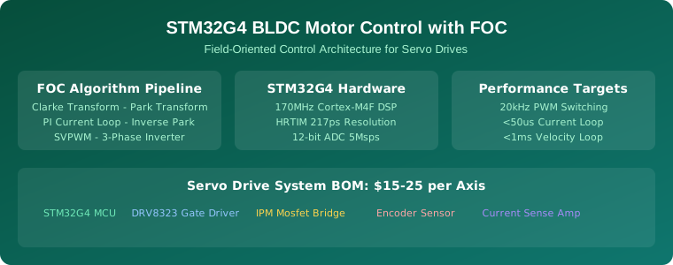
The FOC algorithm follows a well-established pipeline: three-phase currents are measured and converted from the stationary reference frame to the rotating reference frame using Clarke and Park transforms. PI controllers regulate the current in the rotating frame, and the outputs are transformed back via inverse Park and space vector PWM (SVPWM) to generate the three-phase inverter signals.
The key advantage of STM32 motor control over dedicated servo drive ICs is flexibility. With a microcontroller-based approach, engineers can implement custom control algorithms, add sensor fusion, integrate industrial communication protocols, and modify the control strategy without changing hardware.
2. Why STM32G4 for Motor Control
The STM32G4 series is specifically designed for motor control applications. Its 170MHz Arm Cortex-M4F core includes a single-precision floating-point unit (FPU) and DSP instructions that accelerate the trigonometric calculations required for FOC. The high-resolution timer (HRTIM) offers 217ps resolution for PWM generation, enabling precise control at switching frequencies up to 20kHz.
The STM32G4’s integrated 12-bit ADC can sample at up to 5 megasamples per second, with hardware oversampling for improved resolution. Three ADCs can operate in interleaved mode for simultaneous current sensing on all three phases. The CORDIC hardware accelerator further speeds up trigonometric functions used in Clarke and Park transforms.
STMicroelectronics provides the X-CUBE-MCSDK (Motor Control SDK), which includes a ready-to-use FOC library, motor tuning tools like the Motor Pilot and Profiler, and a graphical Motor Control Workbench for parameter configuration. This significantly reduces development time compared to implementing FOC from scratch.
3. Hardware Architecture for Servo Drive
A complete servo drive system based on STM32G4 requires several hardware blocks:
- STM32G474 MCU: The target microcontroller with HRTIM and dual-bank Flash for safe firmware updates.
- Gate Driver: DRV8323 or similar three-phase gate driver with integrated current sense amplifiers and SPI configuration.
- Power Stage: 6x N-channel MOSFETs in a three-phase inverter bridge. IPM (Intelligent Power Module) modules like the STGIPN3H60 simplify design.
- Current Sensing: Two or three shunt resistors with differential amplification, or Hall-effect current sensors for isolated sensing.
- Position Sensor: Incremental encoder (quadrature), Hall sensors, or magnetic angle sensors like the AS5048A for absolute position.
- Communication: CAN FD, RS485 (Modbus), or EtherCAT for industrial network integration.
4. Implementing FOC with STM32 HAL
The ST Motor Control SDK provides a layered architecture. At the lowest level, HAL drivers handle timer, ADC, and GPIO configuration. The middleware layer implements current sensing, Park/Clarke transforms, PI regulators, and SVPWM generation. The application layer implements speed and position control loops.
A typical current loop runs at 20kHz (50µs period). The PI controllers for the direct (d) and quadrature (q) axis currents are tuned using the modulus optimum method. The speed loop runs at a lower frequency (1kHz to 5kHz) and can be tuned using the symmetrical optimum method. Position control adds an outer loop running at 100Hz to 1kHz.
The Motor Control Workbench generates initialization code and parameter files based on motor parameters and hardware configuration. Engineers can then fine-tune the PI gains and current limits through the Motor Pilot GUI without recompiling firmware.
5. Tuning PI Controllers for Performance
Proper PI tuning is critical for servo drive performance. The current loop PI gains are calculated from the motor’s electrical parameters: stator resistance (Rs), inductance (Ld, Lq), and the desired bandwidth. A typical current loop bandwidth is 1-2kHz, which requires PI gains that produce a closed-loop response with minimal overshoot and zero steady-state error.
The STM32 Motor Control SDK includes an auto-tuning feature that measures motor parameters and calculates initial PI gains automatically. Engineers can then refine the gains through step response testing and Bode plot analysis using the Motor Pilot tool.
6. Complete BOM and Cost Analysis
For a single-axis servo drive based on the STM32G4:
- STM32G474 MCU: $4-6
- DRV8323 Gate Driver: $2-3
- 6x N-channel MOSFETs: $2-4
- AS5048A Magnetic Encoder: $3-5
- Current sensing: $1-2
- PCB and passives: $3-5
Total: $15-25 per axis. Compare this to commercial servo drives at $200-500 per axis. For a 3-axis CNC machine or robotic arm, the savings are substantial — $50 vs $1,500.
Frequently Asked Questions
Can STM32G4 control a servo motor without an encoder?
Yes. Sensorless FOC uses the motor’s back-EMF to estimate rotor position. This works well at medium to high speeds but has limitations at low speeds and during startup.
What is the maximum PWM frequency for STM32 motor control?
The STM32G4’s HRTIM can generate PWM up to 20kHz with 217ps resolution. Higher frequencies reduce current ripple but increase switching losses in the MOSFETs.
Is the ST Motor Control SDK free?
Yes. The X-CUBE-MCSDK is free to download from STMicroelectronics and includes the FOC library, Motor Control Workbench, and documentation.
Can I control multiple motors with one STM32G4?
The STM32G474 can control up to two motors simultaneously using its dual HRTIM and dual ADC support.
Related Reading
- STM32G4 for BLDC Motor Control: Building Precision Servo Drives
- ESP32 as an Industrial PLC: Open-Source Automation Controllers
- Digital Twins in Manufacturing 2026
Sources
- STMicroelectronics STM32G4 Series Official Page
- STM32CubeG4 firmware package
- X-CUBE-MCSDK Motor Control SDK
- Texas Instruments DRV8323 Gate Driver Datasheet