Inertia Ratio and Servo Oscillation: Causes, Limits and Fixes
Key Takeaway
Inertia ratio is load inertia divided by motor rotor inertia. Below about 10:1 for general axes and below 5:1 for high-acceleration axes, a servo is easy to tune. Above that, the position loop fights the load inertia, the velocity loop hunts, and the axis oscillates. Fix it with gearing, not gain.
Figure 1: Inertia ratio and servo stability – ratio, tuning, mechanics, fixes
Table of Contents
1. What Inertia Ratio Means
Definition
Inertia ratio is the load inertia referred to the motor shaft, divided by the motor rotor inertia:
inertia ratio = J_load_referred / J_rotor
Load inertia referred to the motor shaft includes everything the motor has to accelerate through the drive train: the coupling, the screw or belt, the pulleys, and the load itself. Each element is divided by the square of the gear ratio between it and the motor.
Why it matters
The motor has to accelerate its own rotor plus everything connected to it. The motor’s torque produces acceleration on the total inertia:
T = (J_rotor + J_load_referred) × alpha
If the load inertia is much larger than the rotor inertia, the motor’s torque is mostly accelerating the load, not the rotor. The motor’s own inertia becomes a small part of the total, and the control loop has to work harder to move the load precisely.
Reflected inertia
Inertia reflected through a gear ratio is divided by the square of the ratio:
J_reflected = J_load / (gear_ratio)^2
A 0.01 kg m^2 load through a 10:1 gearbox appears as 0.01 / 100 = 0.0001 kg m^2 at the motor. Through a 100:1 harmonic drive it appears as 0.01 / 10000 = 0.000001 kg m^2. Gear reduction is the most effective way to reduce reflected inertia.
2. Ratio Limits and the Stability Envelope
General-purpose limit: 10:1
For a general-purpose machine axis (conveyor, positioning table, lifter), an inertia ratio below 10:1 is the practical limit. Below 10:1, a servo drive can usually tune the axis stably with standard gains. Above 10:1, the position loop starts to fight the load inertia, and tuning becomes difficult.
High-acceleration limit: 5:1
For a high-acceleration axis (pick-and-place, insertion, high-speed transfer), the limit is tighter: below 5:1. High acceleration means high torque demand, and high torque demand with high inertia ratio means the motor is working near its limit. The velocity loop hunts, and the axis oscillates.
Where the limit comes from
The limit comes from the velocity loop bandwidth. The velocity loop has to accelerate the total inertia (motor + reflected load). As the reflected load inertia grows, the velocity loop’s effective bandwidth drops. At some point, the velocity loop is too slow to stabilize the position loop, and the axis oscillates.
Motor datasheet limits
Most servo motor datasheets publish a maximum recommended inertia ratio: often 10:1 for general-purpose motors, 5:1 for high-performance motors, and 3:1 or less for ultra-high-performance motors. These are not hard limits; they are guidelines from the manufacturer based on typical tuning.
3. Symptoms of Too Much Inertia Ratio
Hunting
Hunting is the axis oscillating around the commanded position without settling. The motor accelerates, overshoots, decelerates, undershoots, and repeats. The position error never settles within the settling band. Hunting is the most common symptom of too much inertia ratio.
Velocity loop saturation
The velocity loop hits its current limit during acceleration, and the axis accelerates more slowly than commanded. The position error grows during acceleration, and the position loop ramps up its command to catch up. The axis never catches up exactly, and the error oscillates.
Position overshoot
The axis overshoots the target position on every move. The position loop commands too much velocity because it is trying to overcome load inertia, and the momentum carries the axis past the target.
Noise and heat
The motor runs hot even at light load, because the velocity loop is commanding current to fight the load inertia. The drive fan runs constantly, and the motor temperature is higher than expected for the load.
4. Fixes Without Changing the Motor
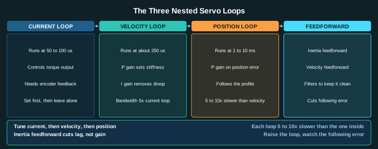
Lower the velocity gain
Reducing velocity loop P gain reduces the stiffness of the velocity loop, which reduces the oscillation. The trade: the axis responds more slowly to velocity commands, and the following error grows during acceleration.
Add a 1st-order filter
Adding a 1st-order low-pass filter on the velocity command or the current command smooths the command and removes high-frequency content. The filter cuts the oscillation but also reduces the bandwidth. A typical filter cutoff is 1.5 to 2 times the position loop bandwidth.
Reduce the position gain
Reducing position P gain reduces the stiffness of the position loop, which reduces the overshoot. The trade: larger following error during moves, and slower settling.
Why these are band-aids
Lowering gains and adding filters reduce the oscillation but they also reduce performance. The axis becomes slower, less accurate, and less responsive. The root cause is still too much reflected inertia at the motor, and the real fix is to reduce the reflected inertia.
5. Gearing as the Primary Fix
Gear ratio divides reflected inertia
Inertia reflected through a gearbox is divided by the square of the gear ratio. A 10:1 gearbox divides the load inertia by 100 at the motor. A 50:1 gearbox divides it by 2500. This is the single most effective way to reduce reflected inertia.
J_reflected_at_motor = J_load / (gear_ratio)^2
Worked example
A belt-driven axis has a load inertia of 0.05 kg m^2 at the load, and a motor rotor inertia of 0.0003 kg m^2. Direct drive (1:1):
ratio = 0.05 / 0.0003 = 167:1
That is far too high; the axis will not tune stably. Add a 5:1 gearbox:
J_reflected = 0.05 / 25 = 0.002 kg m^2
ratio = 0.002 / 0.0003 = 6.7:1
That is below 10:1, and the axis tunes easily.
Gearbox choice
Planetary gearboxes are the most common choice for servo axes: low backlash, high ratio in a single stage, compact. Harmonic drives offer zero backlash and higher ratios but cost more. Belt reductions are cheap but add compliance and backlash.
Trade-offs
- Gear reduction reduces reflected inertia but also reduces output speed. The motor must spin faster for the same output speed.
- Gear reduction multiplies motor torque by the ratio (minus efficiency), so the motor can be smaller.
- Gearboxes add compliance (torsional wind-up) and backlash, which can themselves cause oscillation if the gearbox is not stiff.
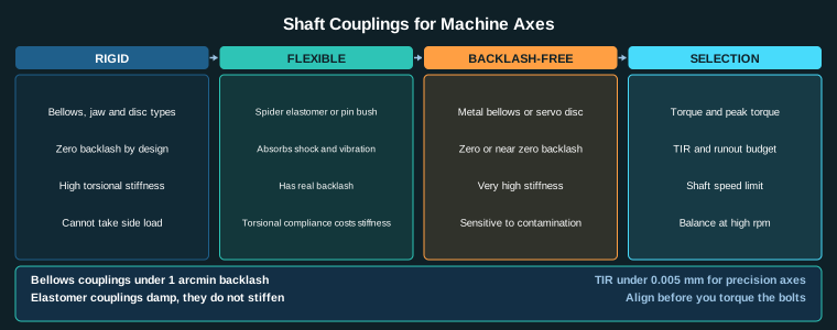
6. Coupling and Drive Train Stiffness
Coupling stiffness
The coupling between the motor and the load twists under torque. A stiff coupling (bellows, disc) twists little; a soft coupling (jaw with spider, Oldham) twists a lot. Torsional wind-up in the coupling appears as position error at the load that the motor cannot see, because the motor is coupled to the other side of the coupling.
Why stiffness matters
A soft coupling between the motor and a high-inertia load is a two-mass system: motor inertia on one side, load inertia on the other, coupled by a spring. The system has a resonant frequency, and if the velocity loop bandwidth is near that frequency, the axis oscillates. A stiffer coupling raises the resonant frequency and makes the axis easier to tune.
Backlash
Backlash in the coupling or the drive train (gearbox teeth, splines, keyways) creates dead zone. The motor moves but the load does not move until the backlash is taken up. The position loop sees no error during the dead zone, then sees a large error when the load catches up. The result is oscillation and poor accuracy.
Practical coupling rules
- Use a bellows or disc coupling for high-inertia-ratio axes: zero backlash, high torsional stiffness.
- Avoid jaw couplings with spiders on high-inertia axes: they have backlash and low torsional stiffness.
- Keep the coupling as short as possible; long couplings twist more.
- Align the coupling carefully; misalignment adds radial load and reduces bearing life.
Related Reading
- Servo Tuning: Position, Velocity and Current Loops Explained
- Shaft Couplings for Machine Axes: Rigid, Flexible and Backlash-Free
- Industrial Motion Control: Complete Guide to Servo, Stepper and Axis Design
- Harmonic Drive Gearbox Selection: Ratio, Repeatability and Life
Sources
- Yaskawa, Servo Motor and Drive Selection Guide (inertia ratio, tuning)
- Rockwell Automation, Servo Drive Inertia Ratio and Tuning
- Siemens, SINAMICS Servo Drive Inertia Ratio Guidelines
- IEC 61800-5-1, Adjustable speed electrical power drive systems: Safety requirements
Key Takeaways
- Inertia ratio = load inertia referred to motor / motor rotor inertia. Keep general axes below 10:1 and high-acceleration axes below 5:1.
- Gear reduction divides reflected inertia by ratio squared; a 10:1 gearbox divides load inertia by 100 at the motor.
- Too much inertia ratio causes hunting, velocity loop saturation, position overshoot, and motor heating.
- Lowering gains and adding filters masks the symptom but reduces performance; reducing reflected inertia fixes the root cause.
- Coupling stiffness and backlash matter: use bellows or disc couplings on high-inertia axes, avoid jaw couplings.