Key Takeaway: SPI communication is the fastest serial protocol available on STM32 and Arduino microcontrollers, reaching speeds above 40 MHz with full-duplex data transfer — making it the preferred choice for high-speed sensors, displays, and SD cards in industrial and hobbyist projects alike.
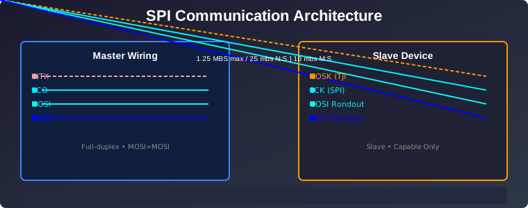
Table of Contents
1. What Is SPI Communication?
SPI communication — short for Serial Peripheral Interface — is a synchronous, full-duplex serial protocol developed by Motorola in the 1980s. It uses a master-slave architecture where one master device controls the clock and initiates all data transfers. Unlike I2C communication, which uses addressing to talk to multiple devices on two wires, SPI communication dedicates a separate chip-select line to each slave device. This eliminates address contention and allows simultaneous clocked data transfer in both directions.
The result is a protocol that easily exceeds 40 MHz on STM32 microcontrollers and runs at 8 MHz or higher on most Arduino boards. That raw speed makes SPI the go-to interface for SD card modules, TFT displays, high-resolution ADCs, digital potentiometers, and RF transceivers — anything where throughput matters more than pin count.
The trade-off is wiring complexity. Each additional slave device requires its own chip-select (SS or CS) line, so a system with four slaves needs five wires from the master (four CS lines plus shared SCK/MOSI/MISO). In industrial environments where wiring harnesses are pre-assembled, this cost is acceptable. In compact consumer designs, I2C’s two-wire bus often wins on simplicity.
2. SPI Wiring for STM32 and Arduino
SPI communication requires four signals between master and slave. Understanding these signals is the foundation of every SPI project:
- SCK (Serial Clock) — Generated by the master, this clock synchronizes every bit transferred. The slave reads data on the clock edges defined by the SPI mode.
- MOSI (Master Out Slave In) — Data flows from master to slave. The master shifts bits onto this line on each clock cycle.
- MISO (Master In Slave Out) — Data flows from slave to master. This enables full-duplex operation: the master can send and receive simultaneously.
- SS or CS (Slave Select / Chip Select) — Active-low signal. The master pulls this line low to select a specific slave before starting a transaction.
STM32 Default SPI Pins
On most STM32 families (F1, F4, G4, H7), the default SPI1 pins are PA5 (SCK), PA6 (MISO), PA7 (MOSI), and PA4 (NSS/CS). SPI2 uses PB13/PB14/PB15/PB12. These can be remapped to alternate pins through the AFIO/mux configuration in STM32CubeMX. The SPI3 peripheral uses PB3 (SCK), PB4 (MISO), PB5 (MOSI).
Arduino Default SPI Pins
On Arduino Uno (ATmega328P), SPI uses pins 13 (SCK), 12 (MISO), 11 (MOSI), and 10 (SS). On Arduino Mega (ATmega2560), SPI is on pins 52 (SCK), 50 (MISO), 51 (MOSI), and 53 (SS). The ESP32 dev boards expose SPI on GPIO 18 (SCK), 19 (MISO), 23 (MOSI), and 5 (CS) — though any GPIO can be remapped via SP.begin() or the ESP-IDF configuration.
Key difference from I2C: I2C uses pull-up resistors on SDA and SCL. SPI communication uses push-pull outputs with no pull-ups needed. This is one reason SPI can run at much higher frequencies — there is no RC delay from pull-up resistors slowing down signal transitions.
3. SPI Modes 0, 1, 2 and 3 Explained
SPI has no protocol-level standard — the mode defines only two things: clock polarity (CPOL) and clock phase (CPHA). Together these determine which clock edge is used to sample data and which edge is used to shift data out.
| Mode | CPOL | CPHA | Idle Clock | Data Sample Edge |
|---|---|---|---|---|
| Mode 0 | 0 | 0 | Low | Rising edge (leading) |
| Mode 1 | 0 | 1 | Low | Falling edge (trailing) |
| Mode 2 | 1 | 0 | High | Falling edge (leading) |
| Mode 3 | 1 | 1 | High | Rising edge (trailing) |
Mode 0 is the most common. Most SPI sensors, displays, and SD card modules default to Mode 0. Always check the datasheet of your slave device before choosing a mode. A mismatch between master and slave SPI modes produces garbled data or no communication at all — one of the most common SPI debugging headaches.
On STM32, the mode is configured in the CR1 register bits CPOL and CPHA. In STM32CubeMX, you simply select “SPI Mode 0” from the dropdown. On Arduino, use SPI.setDataMode(SPI_MODE0) in your setup function, or SPI.beginTransaction(SPISettings(1000000, MSBFIRST, SPI_MODE0)) for transaction-based operation.
4. Speed Comparison: SPI vs I2C vs UART
Choosing the right serial protocol depends on your speed requirements, wiring constraints, and how many devices share the bus. Here is how the three most common protocols compare:
| Feature | SPI | I2C | UART |
|---|---|---|---|
| Max Speed | 40–100 MHz | 400 kHz (std), 3.4 MHz (fast+) | 1–3 Mbps (typically) |
| Data Lines | 4+ (per slave adds CS) | 2 (SDA + SCL) | 2 (TX + RX) |
| Duplex | Full-duplex | Half-duplex | Full-duplex |
| Addressing | Hardware (CS pin) | Software (7-bit address) | Point-to-point only |
| Multi-Slave | 1 per CS line | Up to 127 on one bus | 1 per UART |
| Clock | Synchronous (SCK) | Synchronous (SCL) | Asynchronous (baud rate) |
| Best For | Displays, SD cards, ADCs, RF | Sensors, EEPROMs, expanders | GPS, Bluetooth modules, debug |
SPI communication wins on raw throughput. When you need to push a 320×240 16-bit TFT display at 30 frames per second, you need roughly 4.6 Mbps — easily within SPI’s capability but impossible for I2C. UART wins on simplicity for point-to-point connections. I2C wins when you have many low-speed devices on a minimal wiring bus.
Read more about the I2C comparison in our UART serial communication guide.
5. Setting Up SPI on STM32 with HAL
Setting up SPI communication on an STM32 microcontroller using the HAL library involves three steps: CubeMX configuration, peripheral initialization, and the transfer function call.
CubeMX Configuration
- Enable the SPI peripheral (SPI1, SPI2, or SPI3) in Connectivity settings.
- Select “Full-Duplex Master” mode.
- Set the baud rate prescaler (e.g., /2 for 60 MHz clock on APB2, yielding 30 MHz SPI clock).
- Set CPOL and CPHA to match your slave device (Mode 0: CPOL=0, CPHA=0).
- Configure CS pin (PA4 for SPI1) as GPIO Output with initial state High.
HAL Transfer Code
The HAL library provides blocking and non-blocking SPI transfer functions:
// Blocking full-duplex transfer
uint8_t txData[] = {0x9F, 0x00, 0x00, 0x00}; // Read JEDEC ID command
uint8_t rxData[4];

HAL_GPIO_WritePin(GPIOA, GPIO_PIN_4, GPIO_PIN_RESET); // CS low
HAL_SPI_TransmitReceive(&hspi1, txData, rxData, 4, 100);
HAL_GPIO_WritePin(GPIOA, GPIO_PIN_4, GPIO_PIN_SET); // CS high

// Non-blocking (DMA-backed) transfer
HAL_SPI_TransmitReceive_DMA(&hspi1, txData, rxData, 4);
The blocking HAL_SPI_TransmitReceive function is fine for initialization sequences and configuration writes. For data-heavy operations like reading from an SD card or refreshing a display, use the DMA variant to keep the CPU free for other tasks. Our STM32 Timer Interrupts guide covers how to combine DMA with timer-triggered transfers for precise sampling.
6. Arduino SPI Library: Quick Start
The Arduino SPI library provides a straightforward API for SPI communication. The key improvement in modern Arduino SPI usage is the transaction-based approach, which prevents conflicts when multiple SPI devices share the same bus.
#include <SPI.h>

const int CS_PIN = 10;

void setup() {
  Serial.begin(115200);
  SPI.begin();
  pinMode(CS_PIN, OUTPUT);
  digitalWrite(CS_PIN, HIGH);
}

void readSensor() {
  SPI.beginTransaction(SPISettings(4000000, MSBFIRST, SPI_MODE0));
  digitalWrite(CS_PIN, LOW);

  byte command = 0x03; // Read register command
  byte response = SPI.transfer(command);

  digitalWrite(CS_PIN, HIGH);
  SPI.endTransaction();

  Serial.println(response, HEX);
}

void loop() {
  readSensor();
  delay(1000);
}
SPISettings takes three arguments: clock speed (Hz), bit order (MSBFIRST or LSBFIRST), and SPI mode. Always wrap SPI transactions in beginTransaction() and endTransaction() when using multiple devices — this ensures each device gets the correct mode and speed even if the other device requires different settings.
For the ESP32, the SPI library also supports configurable pins. Use SPI.begin(SCK, MISO, MOSI, SS) to assign any GPIO to the SPI function.
7. DMA Transfers for High-Speed Data
Direct Memory Access (DMA) is the key to extracting maximum SPI performance from STM32 microcontrollers. When SPI communication runs through DMA, the CPU is free to process data from the previous transfer while the DMA controller handles the next block automatically.
Consider a typical industrial scenario: reading a 16-bit ADC at 100 kHz sampling rate over SPI. Without DMA, the CPU would spend most of its time in the SPI transfer loop. With DMA configured in circular mode, the DMA controller fills a double buffer automatically while the CPU processes the completed half-buffer — a classic ping-pong pattern.
STM32 DMA SPI Configuration
- In CubeMX, enable DMA for SPI1_TX and SPI1_RX.
- Set DMA mode to “Circular” for continuous transfers, or “Normal” for single-shot.
- Configure the DMA data width as “Half Word” (16-bit) for 16-bit sensors.
- Enable the DMA half-transfer and transfer-complete interrupts for the ping-pong pattern.
On Arduino, DMA SPI is not natively supported by the standard library. However, on the ESP32, the ESP-IDF SPI driver supports DMA internally through spi_device_transmit when you set the DMA channel in the bus configuration. For STM32, DMA SPI is the recommended approach for any data rate above 1 MHz.
8. Debugging SPI Communication Issues
SPI communication is generally more reliable than I2C because it lacks address contention and bus arbitration issues. However, several common pitfalls can cause failures in embedded projects:
Wrong SPI Mode
The most frequent SPI bug is a CPOL/CPHA mismatch. If the slave device expects Mode 0 (CPOL=0, CPHA=0) but the master is configured for Mode 3 (CPOL=1, CPHA=1), data will be shifted by half a clock period, producing corrupted bytes. Check the datasheet. When in doubt, start with Mode 0 and test all four modes.
Missing Pull-Up on CS Line
The CS line must be held HIGH when idle. If the CS pin floats during reset or power-up, the slave may start receiving garbage data before the master initializes. Add a 10kΩ pull-up resistor to 3.3V on the CS line for production designs.
Signal Integrity at High Speed
At SPI speeds above 10 MHz, signal integrity becomes critical. Keep SPI traces short (under 5 cm on a PCB), use ground plane under the traces, and avoid routing SCK near noisy signals like motor PWM or relay drivers. On breadboard prototypes, limit SPI clock to 4 MHz to avoid crosstalk from long jumper wires.
Logic Level Mismatch
STM32 GPIOs are 3.3V. If your slave device is 5V-only (older Arduino shields, for example), you need a bidirectional level shifter on MOSI, MISO, and SCK. A BSS138-based level shifter board costs under $1 and prevents damage to 3.3V devices. Note that many STM32 GPIO pins are 5V tolerant on the input side, but the output is still 3.3V — verify with your specific part number.
Using a Logic Analyzer
A logic analyzer is the fastest way to diagnose SPI issues. Capture all four SPI lines simultaneously, decode the SPI protocol in the analyzer software (Saleae Logic, sigrok/PulseView), and verify that the MOSI data, MISO response, clock edges, and CS timing all match your expectations. If you need more guidance, see our Oscilloscope vs Logic Analyzer comparison.
Frequently Asked Questions
What is the maximum SPI speed on STM32?
SPI communication on STM32 can reach 100 MHz on the H7 family and 40 MHz on the F4 family, depending on the APB bus clock and prescaler settings. The practical limit for most embedded designs is 20–30 MHz due to PCB trace length and signal integrity constraints.
Can I use SPI and I2C at the same time on STM32?
Yes. SPI and I2C are independent peripherals on STM32 microcontrollers. You can run SPI on SPI1 and I2C on I2C1 simultaneously without any conflict. In fact, many industrial designs use SPI for high-speed peripherals (displays, ADCs) and I2C for low-speed sensors (temperature, humidity) on the same board.
How many devices can share one SPI bus?
SPI communication supports as many slave devices as there are available chip-select pins on the master. Each device needs its own CS line. On STM32, you can use any GPIO as a software CS pin, so the practical limit is the number of free GPIOs — often 8–16 devices on a full-featured STM32H7.
What is the difference between SPI Mode 0 and Mode 3?
In Mode 0, the clock idles LOW and data is sampled on the rising (leading) edge. In Mode 3, the clock idles HIGH and data is sampled on the rising (trailing) edge. Both modes sample data on the same physical clock edge, but the idle state differs. Always check the slave datasheet to determine the correct SPI mode.
Is SPI better than UART for industrial sensors?
It depends on the sensor. SPI communication offers higher speed and full-duplex operation, making it better for high-resolution ADCs and displays. UART is simpler to wire (2 wires, no clock) and works well over longer distances (up to 15 meters at low baud rates), making it preferred for industrial sensors that communicate via Modbus or RS485. Read our UART guide for details.
Related Reading
- I2C Communication Complete Guide for STM32 and Arduino
- UART Serial Communication Guide on STM32 and Arduino
- CAN Bus for Industrial Systems Guide
- STM32 vs Arduino for Industrial Automation
- Industrial ADC Techniques with STM32
Sources
- STM32H7 Reference Manual — SPI Peripheral Description
- Arduino SPI Library Reference
- ESP32-S3 Datasheet — SPI Interface Specifications
- Texas Instruments: Understanding the SPI Interface
- Jack Ganssle — The Art and Science of Embedded Systems (Serial Communication Chapter)
Disclosure: This post contains affiliate links to products on Amazon. We may earn a commission at no extra cost to you if you purchase through these links. Prices and availability are subject to change. We only recommend products we have personally tested or thoroughly researched.