Harmonic Drive Gearbox Selection: Ratio, Repeatability and Life
Key Takeaway
Harmonic drive selection follows three numbers: ratio, rated load and repeatability. The ratio sets the speed reduction and the torque multiplication, the load sets the gearbox size, and repeatability decides whether the axis can hold position.
Figure 1: Harmonic drive selection – ratio, load, accuracy, mounting
Table of Contents
1. How a Harmonic Drive Works
A harmonic drive is a gearbox with no gear teeth in the conventional sense. It has three elements: a wave generator, a flex spline and a circular spline. The wave generator is an oval cam on the motor shaft. It deforms the flex spline into an oval, and the teeth of the flex spline engage with the circular spline at two opposite points. As the wave generator rotates, those engagement points move around, and the flex spline crawls around the circular spline one tooth at a time.
The consequence: a reduction ratio of 30:1 to 160:1 in a single stage, zero backlash because there are two engagement points always loaded, and a compact envelope. There is no gearbox oil, no bearing to wear in the conventional sense, and no clutch to slip.
The elements
- Wave generator.An oval cam, usually on a ball bearing, mounted on the motor shaft. It is the input.
- Flex spline.A thin, flexible steel cup with external teeth on its outer diameter. It is deformed by the wave generator and its teeth engage the circular spline.
- Circular spline.A rigid ring with internal teeth, fixed to the housing. It has two more teeth than the flex spline, and that difference is what creates the reduction.
2. Ratio and Torque Multiplication
The reduction ratio is determined by the tooth count difference between the circular spline and the flex spline. If the circular spline has N teeth and the flex spline has N−2, one revolution of the wave generator moves the flex spline by two teeth around the circular spline. The output turns by 2/N of a revolution per input revolution, so the ratio is N/2 : 1.
ratio = N_circular / 2
For a 200-tooth circular spline and a 198-tooth flex spline, the ratio is 100:1. That is the typical range: 30:1 at the small end, up to 160:1 or even 320:1 for large units.
Torque multiplication
Ignoring losses, output torque equals input torque times ratio times efficiency:
T_out = T_in × ratio × efficiency
With a 5 Nm motor, a 100:1 harmonic drive and 85 percent efficiency, the output is 5 x 100 x 0.85 = 425 Nm. That is why a small motor can drive a large load: the gearbox does the multiplication, and the motor only has to overcome inertia and friction.
Reflected inertia
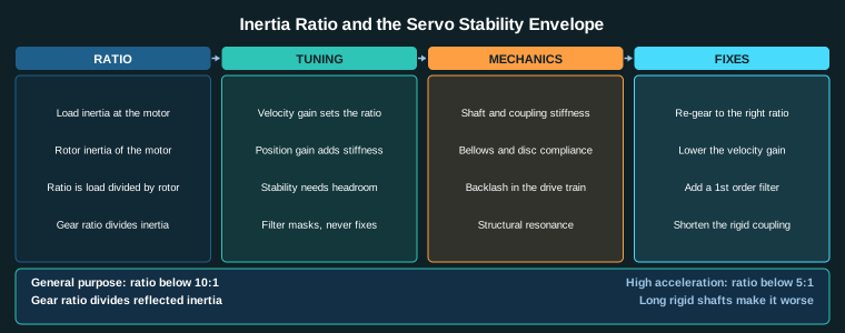
The load inertia reflected to the motor is divided by the square of the ratio:
J_reflected = J_load / ratio^2
A 0.01 kg m^2 load reflected through a 100:1 ratio appears as 0.01 / 10000 = 1e-6 kg m^2 at the motor. That is negligible, which is why harmonic drives make small motors look stiff and why the position loop is easy to tune.
3. Load and Life
Harmonic drive selection starts with the load, because the gearbox is sized for it. The rating has two numbers: rated torque and peak torque. Rated torque is continuous. Peak torque is for acceleration and deceleration, and it is usually 1.5 to 3 times rated.
Load calculation
Work out the torque at the output shaft: the load torque plus the acceleration torque plus any external force transmitted through the load. Then multiply by 1.2 for a margin, and check it against rated torque. Then check peak torque against the highest torque the machine ever asks for, including emergency stops.
T_required = T_load + T_accel + T_external
T_peak_required = max torque in any 100 ms window
Life
Harmonic drive life is rated in hours, typically 10,000 to 20,000 hours at rated load. The life scales with the cube of the load ratio: halving the load increases life by roughly eight times. Doubling the load reduces life to one eighth. That is why running a harmonic drive near its rating is cheap in the short term and expensive in the long term.
Shock loads
A harmonic drive does not tolerate shock well. A sudden impact on the output shaft, a crash into a limit, or a jammed workpiece can damage the flex spline teeth. If the machine can shock the gearbox, add a torque limiter or a clutch between the motor and the gearbox.
4. Accuracy and Repeatability
Lost motion
Lost motion is the total angular play between input and output when the direction reverses. A harmonic drive has effectively zero lost motion under load because the two engagement points are always preloaded against each other. At zero load there is a tiny amount, usually under 1 arcminute (0.017 degrees). That is backlash free for practical purposes.
Repeatability
Repeatability is the spread when the axis returns to the same position repeatedly. A harmonic drive is typically under 1 arcminute (0.017 degrees) repeatable, and some precision units are under 30 arcseconds (0.008 degrees). That is the number that matters for a positioning axis, not the ratio.
Hysteresis
Hysteresis is the difference between the output position when approaching a target from one direction versus the other. A harmonic drive has low hysteresis because the flex spline teeth are always engaged at two points, but it is not zero. At high precision, hysteresis can be 1 to 3 arcminutes.
5. Mounting and the Output Shaft
Coaxial mounting
A harmonic drive is coaxial: input and output share the same axis. The motor mounts inline with the load, which keeps the envelope small and eliminates couplings between the motor and the gearbox. The motor shaft couples directly to the wave generator, usually with a bellows or bellows-like coupling to absorb small misalignment.
Flex spline and circular spline mounting
The flex spline is the output. It is usually mounted to the load with bolts around its outer diameter, or through a hollow output shaft. The circular spline is fixed to the housing and does not rotate. Both need flat, stiff mounting surfaces; any flex in the mounting shows up as lost motion at the output.
Avoid side load
The flex spline teeth are thin and the wave generator applies a concentrated radial force. Do not overhung a load on the output shaft, do not mount a pulley or a sprocket that creates a bending moment, and do not use the gearbox as a structural member. The output shaft carries torque and a small axial load, but not a side load.
6. Selection Summary
Work the decision in this order:
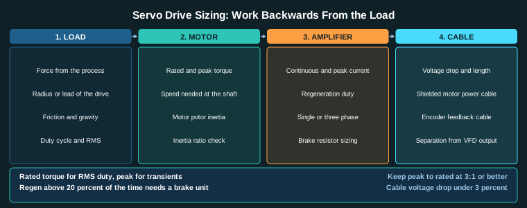
- Ratio.Decide the output speed from the load requirement, then the ratio from the motor speed. A 3000 rpm motor with a 100:1 ratio gives 30 rpm output.
- Rated torque.Check the continuous output torque against the load torque with margin.
- Peak torque.Check acceleration and emergency-stop torque against peak rating.
- Repeatability.Confirm the required arc-second or arc-minute repeatability is within the unit’s rating.
- Life.Estimate running hours at the actual load. Halve the load, octuple the life.
- Mounting.Confirm coaxial output, no side load, stiff mounting surfaces.
The harmonic drive is the right choice when you need high ratio, zero backlash and high repeatability in a small envelope. It is the wrong choice when the load shocks, when the output needs a side load, or when the duty cycle is so high that the gearbox runs hot continuously.
Related Reading
- Inertia Ratio and Servo Oscillation: Causes, Limits and Fixes
- Servo Tuning: Position, Velocity and Current Loops Explained
- Shaft Couplings for Machine Axes: Rigid, Flexible and Backlash-Free
- Industrial Motion Control: Complete Guide to Servo, Stepper and Axis Design
Sources
- HDS Drive, Harmonic Drive Gearbox Technical Catalog (ratios, torque, life)
- Whitstein, Harmonic Drive and Gearhead Selection Guide
- Nabtesco, RV and Harmonic Reducer Catalog
- ISO 9283, Machine tools: Test conditions for positioning accuracy and repeatability
Key Takeaways
- A harmonic drive gives reduction of 30:1 to 160:1 in a single stage with zero backlash under load and repeatability under 1 arcminute.
- Output torque equals input torque times ratio times efficiency; reflected load inertia is divided by ratio squared.
- Life is rated in hours at rated load and scales with the cube of the load ratio: halve the load, octuple the life.
- Do not side-load the output; mount both splines to stiff, flat surfaces; use a torque limiter if the load can shock.
- Select ratio first, then rated and peak torque, then repeatability and life.